HP ProLiant BL490c HP ProLiant BL490c G6 Server Blade User Guide - Page 8
Mezzanine connector definitions, System maintenance switch, System maintenance switch procedures - g6
 |
View all HP ProLiant BL490c manuals
Add to My Manuals
Save this manual to your list of manuals |
Page 8 highlights
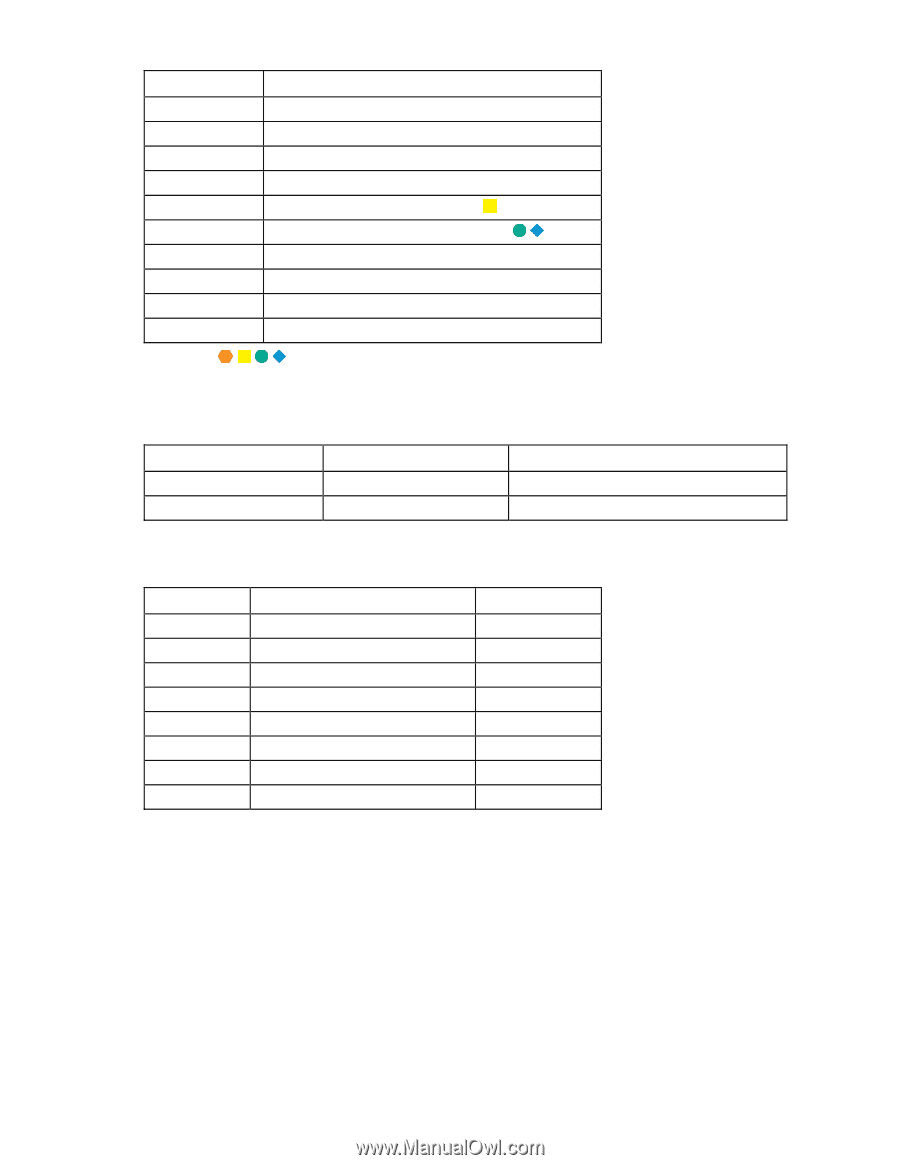
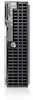
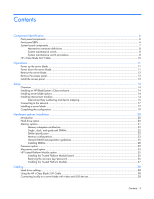
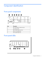
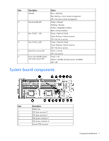
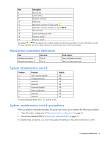
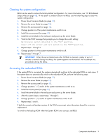
Item Description 7 SD card slot 8 System battery 9 Enclosure connector 10 Battery tray 11 Mezzanine connector 1 (Type I only) 12 Mezzanine connector 2 (Type I or Type II) 13 TPM connector 14 System maintenance switch 15 Processor socket 2 16 Processor socket 1 The symbols correspond to the symbols located on the interconnect bays. For more information, see the HP ProLiant BL490c G6 Server Blade Installation Instructions that ship with the server blade. Mezzanine connector definitions Item Mezzanine connector 1 Mezzanine connector 2 Connector PCIe x8 PCIe x8 Card support Type I mezzanine card only Type I or II mezzanine card System maintenance switch Position Function Default 1* iLO 2 security override Off 2 Configuration lock Off 3 Reserved Off 4 Reserved Off 5* Password disabled Off 6* Reset configuration Off 7 Reserved Off 8 Reserved Off *To access redundant ROM, set S1, S5, and S6 to ON. System maintenance switch procedures When you perform troubleshooting steps, this guide may instruct you to perform the following procedures: • Clear the system configuration ("Clearing the system configuration" on page 9). • Access the redundant ROM ("Accessing the redundant ROM" on page 9). To complete these procedures, you must change physical settings on the system maintenance switch. Component identification 8
-
 1
1 -
2
-
 3
3 -
 4
4 -
 5
5 -
 6
6 -
 7
7 -
 8
8 -
 9
9 -
 10
10 -
 11
11 -
 12
12 -
 13
13 -
14
-
15
-
16
-
17
-
18
-
19
-
20
-
21
-
22
-
23
-
24
-
25
-
26
-
27
-
28
-
29
-
30
-
31
-
32
-
33
-
34
-
35
-
36
-
37
-
38
-
39
-
40
-
41
-
42
-
43
-
44
-
45
-
46
-
47
-
48
-
49
-
50
-
51
-
52
-
53
-
54
-
55
-
56
-
57
-
58
-
59
-
60
-
61
-
62
-
63
-
64
-
65
-
66
-
67
-
68
-
69
-
70
-
71
-
72
-
73
-
74
-
75
-
76
-
77
-
78
-
79
-
80
-
81
-
82
-
83
-
84
-
85
-
86
-
87
-
88
-
89
-
90
-
91
-
92
-
93
-
94
-
95
-
96
-
97
-
98
-
99
-
100
-
101
 |
 |