HP ProLiant SL4545 HP ProLiant SL4500 Series Setup and Installation Guide
HP ProLiant SL4545 Manual
 |
View all HP ProLiant SL4545 manuals
Add to My Manuals
Save this manual to your list of manuals |
HP ProLiant SL4545 manual content summary:
- HP ProLiant SL4545 | HP ProLiant SL4500 Series Setup and Installation Guide - Page 1
and Installation Guide Abstract This document contains setup, installation, and configuration information for the HP ProLiant SL4500 Series. This document is for the person who installs, administers, and troubleshoots servers and storage systems. HP assumes you are qualified in the servicing of - HP ProLiant SL4545 | HP ProLiant SL4500 Series Setup and Installation Guide - Page 2
to change without notice. The only warranties for HP products and services are set forth in the express warranty statements accompanying such products and services. Nothing herein should be construed as constituting an additional warranty. HP shall not be liable for technical or editorial errors - HP ProLiant SL4545 | HP ProLiant SL4500 Series Setup and Installation Guide - Page 3
side mounting 39 Powering up the system...41 Hot-plug power supply calculations...41 Troubleshooting ...42 Important safety information...42 Symbols on equipment ...42 Troubleshooting resources ...43 Electrostatic discharge ...44 Preventing electrostatic discharge ...44 Grounding methods to prevent - HP ProLiant SL4545 | HP ProLiant SL4500 Series Setup and Installation Guide - Page 4
Before you contact HP...45 HP contact information ...45 Customer Self Repair ...45 Regulatory compliance notices ...53 Regulatory compliance identification numbers 53 Federal Communications Commission notice 53 FCC rating label...53 - HP ProLiant SL4545 | HP ProLiant SL4500 Series Setup and Installation Guide - Page 5
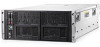
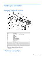
Planning the installation Verifying the pallet contents Item Description 1 The HP ProLiant SL4500 Series chassis 2 Nodes* 3 Drive blank* 4 Drive* 5 Power supply blank* 6 Management module 7 Power supply* 8 I/O modules* 9 System fans (5) 10 Access panel 11 Rack rails and cable - HP ProLiant SL4545 | HP ProLiant SL4500 Series Setup and Installation Guide - Page 6
safety requirements and guidelines for manual material handling. • Remove to the equipment, you must adequately support the chassis during installation and removal. Perform service on system components only as instructed in the troubleshooting. Space and airflow requirements To enable servicing - HP ProLiant SL4545 | HP ProLiant SL4500 Series Setup and Installation Guide - Page 7
the back of the rack to the rear of another rack or row of racks. HP rack products draw cool air in through the front and expel warm air through the rear improper cooling that can lead to thermal damage. Racks provide proper server cooling from flow-through perforations in the front and rear doors - HP ProLiant SL4545 | HP ProLiant SL4500 Series Setup and Installation Guide - Page 8
branch wiring and receptacles, are listed or certified grounding-type devices. Because of the high ground-leakage currents associated with this equipment, HP recommends the use of a PDU that is either permanently wired to the building's branch circuit or includes a nondetachable cord that is wired - HP ProLiant SL4545 | HP ProLiant SL4500 Series Setup and Installation Guide - Page 9
Component and LED identification Front panel components • 1 node chassis Item 1 2 3 4 5 6 7 8 9 10 11 Description Node hard drives LFF drive health LED LFF drive UID Drives controlled by the array controller a. Port 1i b. Port 2i Drive display boards Node VGA connector Node USB connectors Node - HP ProLiant SL4545 | HP ProLiant SL4500 Series Setup and Installation Guide - Page 10
• 2 node chassis Item 1 2 3 4 5 6 7 8 9 10 11 12 13 14 Description Node 1 Node hard drives LFF drive health LED LFF drive UID Drives controlled by node 1 P420i array controller Node 2 Drives controlled by node 2 P420i array controller Drive display boards Node VGA connector Node USB connectors - HP ProLiant SL4545 | HP ProLiant SL4500 Series Setup and Installation Guide - Page 11
drive is selected. Hard drive health LEDs LED behavior Definition Off System is off. Green Amber Storage system health is good. System requires service or a fault is detected. Check hard drives, hard drive backplane, RAID controller, and system fans. UID LEDs LED behavior Off Blue flashing - HP ProLiant SL4545 | HP ProLiant SL4500 Series Setup and Installation Guide - Page 12
Node front panel LEDs and buttons Item 1 2 3 4 Description UID LED button Node release button System Health LED Power On/Standby button and system power LED Status Blue = Activated Flashing blue = System is being remotely managed or firmware update is in progress. Off = Deactivated - Green = - HP ProLiant SL4545 | HP ProLiant SL4500 Series Setup and Installation Guide - Page 13
Item 1 2 3 4 Description System fans I/O module Management module Power supplies • 2 node chassis Item 1 2 3 4 5 Description System fans I/O module for node 1 Management module Power supplies I/O module for node 2 I/O module connectors and LEDs • 1 Gb I/O module Component and LED - HP ProLiant SL4545 | HP ProLiant SL4500 Series Setup and Installation Guide - Page 14
Item 1 2 3 4 5 Description Activity LED 1Gb connectors I/O module health LED Serial connector Link LED • 10 Gb I/O module Item 1 2 3 4 5 6 7 8 9 Description 1 Gb connectors I/O module health LED QSFP 10 Gb Ethernet or 40Gb IB connector, depending on configuration SFP+ 10Gb Ethernet connector - HP ProLiant SL4545 | HP ProLiant SL4500 Series Setup and Installation Guide - Page 15
Description Status 10Gb/40Gb link LED Green = Network link Off = No network link 10Gb/40Gb activity Flashing amber = Network activity LED Off = No network activity Management module connectors and LEDs Item 1 2 3 4 5 Description UID LED Health LED Description RCM connector (SL-APM) - HP ProLiant SL4545 | HP ProLiant SL4500 Series Setup and Installation Guide - Page 16
Device bay numbering Power supply LED Power LED Off Green Status • No AC power to power supply units. Check the AC power cord. • AC is present. Standby output is on; output is disabled. • Power supply failure (includes overvoltage and overtemperature) AC is present and main 12 V output is enabled - HP ProLiant SL4545 | HP ProLiant SL4500 Series Setup and Installation Guide - Page 17
LED color Off Solid amber System fan status The fan is working or power is off. The fan module has failed. Component and LED identification 17 - HP ProLiant SL4545 | HP ProLiant SL4500 Series Setup and Installation Guide - Page 18
Installation Installation overview To set up and install the chassis: 1. Set up and install the rack. For more information, see the documentation that ships with the rack. 2. Disassemble the chassis ("Disassembling the chassis" on page 18). 3. Install the chassis into the rack ("Installing the - HP ProLiant SL4545 | HP ProLiant SL4500 Series Setup and Installation Guide - Page 19
b. Power supplies Installation 19 - HP ProLiant SL4545 | HP ProLiant SL4500 Series Setup and Installation Guide - Page 20
c. Management module. Loosen the screw securing the management module to the chassis, and then remove the module. d. I/O module CAUTION: To avoid damage to the node, always support the bottom of the node when removing it from the chassis. Installation 20 - HP ProLiant SL4545 | HP ProLiant SL4500 Series Setup and Installation Guide - Page 21
e. Node CAUTION: To avoid damage to the device, do not use the removal handle to carry it. 2. Remove the access panel: a. Release the access panel latch. b. Slide the access panel back about 1.5 cm (0.5 in). c. Lift and remove the access panel. 3. Remove all drives: IMPORTANT: Labels are provided so - HP ProLiant SL4545 | HP ProLiant SL4500 Series Setup and Installation Guide - Page 22
support the manual HP ProLiant SL4500 Series. • Be sure sufficient clearance exists for cabling, installation and removal of the chassis, and actuation of the rack doors. The chassis requires installation in a rack. To install the rack rails, see the Quick Deploy Rail System Installation Instructions - HP ProLiant SL4545 | HP ProLiant SL4500 Series Setup and Installation Guide - Page 23
You can install up to three chassis in a 36U rack. If you are installing more than one chassis, install the first chassis in the bottom of the rack, and then install additional chassis by moving up the rack with each subsequent chassis. Plan rack installation carefully, because it is difficult to - HP ProLiant SL4545 | HP ProLiant SL4500 Series Setup and Installation Guide - Page 24
3. Push in the release lever, and then install the chassis into the rack. 4. For round-hole racks, remove the guide pins and replace them with the guide pins included for round-hole racks. Installation 24 - HP ProLiant SL4545 | HP ProLiant SL4500 Series Setup and Installation Guide - Page 25
5. Attach a cage nut to each side of the rack. 6. Align the blanking panel. 7. Secure the blanking panel to the rack. Installation 25 - HP ProLiant SL4545 | HP ProLiant SL4500 Series Setup and Installation Guide - Page 26
the component as indicated. Installing a drive To install the component: 1. Prepare the drive. IMPORTANT: The 1 node chassis supports up to 30 drives per drive backplane. The 2 node chassis supports up to 25 drives per drive backplane. Always populate drive bays from the rear to the front starting - HP ProLiant SL4545 | HP ProLiant SL4500 Series Setup and Installation Guide - Page 27
on or pinched by items placed against it. Pay particular attention to the plug, electrical outlet, and the point where the cord extends from the server. Installation 27 - HP ProLiant SL4545 | HP ProLiant SL4500 Series Setup and Installation Guide - Page 28
To install the component: Insert the power supply into the device bay, and then press firmly until the power supply is seated. Installing the system fan To install the component: Push in on the tabs, and then insert the system fan into the chassis. IMPORTANT: Use the tabs to insert the system fan - HP ProLiant SL4545 | HP ProLiant SL4500 Series Setup and Installation Guide - Page 29
WARNING: To reduce the risk of electric shock, fire, or damage to the equipment, do not plug telephone or telecommunications connectors into RJ-45 connectors. To install the component: 1. Release the I/O handle, and then push the I/O handle down. 2. Insert the I/O module into the chassis, and be - HP ProLiant SL4545 | HP ProLiant SL4500 Series Setup and Installation Guide - Page 30
up to lock it into place. 4. Secure the management module to the chassis. I/O module options Installing an expansion board The following instructions apply to both 1Gb and 10Gb I/O module configurations. 1. Power down the node. 2. Disconnect any cables connected to the I/O module. Installation 30 - HP ProLiant SL4545 | HP ProLiant SL4500 Series Setup and Installation Guide - Page 31
3. Remove the I/O module. 4. Remove the access panel. 5. Remove the expansion board blank. Installation 31 - HP ProLiant SL4545 | HP ProLiant SL4500 Series Setup and Installation Guide - Page 32
6. Install the expansion board bracket. 7. Install the expansion board, and then secure it with two screws. Installation 32 - HP ProLiant SL4545 | HP ProLiant SL4500 Series Setup and Installation Guide - Page 33
8. Attach the low profile bracket to any supported low profile option card. For a list of supported option cards, see the QuickSpecs on the HP website (http://www.hp.com). 9. Install the option card. 10. Install the access panel. 11. Install the I/O module. 12. Connect any cables to the I/O module. - HP ProLiant SL4545 | HP ProLiant SL4500 Series Setup and Installation Guide - Page 34
3. Remove the I/O module. 4. Remove the access panel. 5. If installed, remove any low profile option card. Installation 34 - HP ProLiant SL4545 | HP ProLiant SL4500 Series Setup and Installation Guide - Page 35
6. If installed, remove the expansion board. 7. If installed, remove the expansion board bracket. Installation 35 - HP ProLiant SL4545 | HP ProLiant SL4500 Series Setup and Installation Guide - Page 36
8. Remove the Smart Array controller and battery. 9. Install the following items on the 10Gb assembly: a. Smart Array controller and battery b. Expansion board bracket, if necessary c. Expansion board, if necessary d. Low profile option card, if necessary e. Access panel 10. Install the I/O module - HP ProLiant SL4545 | HP ProLiant SL4500 Series Setup and Installation Guide - Page 37
components. See the HP ProLiant SL Servers Site Planning Guide on the Documentation CD or the HP website (http://www.hp.com) for additional management arm on the rear right-hand side of the rack, see the instructions in "Converting the cable management arm for opposite side mounting." Perform these - HP ProLiant SL4545 | HP ProLiant SL4500 Series Setup and Installation Guide - Page 38
Cabling and powering up the chassis 38 - HP ProLiant SL4545 | HP ProLiant SL4500 Series Setup and Installation Guide - Page 39
Converting the cable management arm for opposite side mounting The cable management arm is designed for ambidextrous implementation. You can convert the arm for right-hand swing. NOTE: To access some components on the rear of the product, you may need to remove the cable management arm. IMPORTANT: - HP ProLiant SL4545 | HP ProLiant SL4500 Series Setup and Installation Guide - Page 40
Cabling and powering up the chassis 40 - HP ProLiant SL4545 | HP ProLiant SL4500 Series Setup and Installation Guide - Page 41
button on the node. Hot-plug power supply calculations For hot-plug power supply specifications and calculators to determine electrical and heat loading for the server, refer to the HP Enterprise Configurator website (http://h30099.www3.hp.com/configurator/). Cabling and powering up the chassis 41 - HP ProLiant SL4545 | HP ProLiant SL4500 Series Setup and Installation Guide - Page 42
sections before troubleshooting the server. Important safety information Before servicing this product, read the Important Safety Information document provided with the server. Symbols local occupational health and safety requirements and guidelines for manual material handling. Troubleshooting 42 - HP ProLiant SL4545 | HP ProLiant SL4500 Series Setup and Installation Guide - Page 43
) • Simplified Chinese (http://www.hp.com/support/ProLiant_TSG_v1_sc) The HP ProLiant Gen8 Troubleshooting Guide, Volume II: Error Messages provides a list of error messages and information to assist with interpreting and resolving error messages on ProLiant servers and server blades. To view the - HP ProLiant SL4545 | HP ProLiant SL4500 Series Setup and Installation Guide - Page 44
workstations. Wear the straps on both feet when standing on conductive floors or dissipating floor mats. • Use conductive field service tools. • Use a portable field service kit with a folding static-dissipating work mat. If you do not have any of the suggested equipment for proper grounding - HP ProLiant SL4545 | HP ProLiant SL4500 Series Setup and Installation Guide - Page 45
Health System log (HP ProLiant Gen8 or later products) Download and have available an Active Health System log for 3 days before the failure was detected. For more information, see the HP iLO 4 User Guide or HP Intelligent Provisioning User Guide on the HP website (http://www.hp.com/go/ilo/docs - HP ProLiant SL4545 | HP ProLiant SL4500 Series Setup and Installation Guide - Page 46
required, you can call the HP Technical Support Center and a technician will help you over the telephone. HP specifies in the materials shipped est obligatoire. Si vous demandez à HP de remplacer ces pièces, les coûts de déplacement et main d'œuvre du service vous seront facturés. Facultatif - Piè - HP ProLiant SL4545 | HP ProLiant SL4500 Series Setup and Installation Guide - Page 47
optional ist. Diese Teile sind auch für Customer Self Repair ausgelegt. Wenn Sie jedoch den Austausch dieser Teile von HP vornehmen lassen möchten, können bei diesem Service je nach den für Ihr Produkt vorgesehenen Garantiebedingungen zusätzliche Kosten anfallen. Support and other resources 47 - HP ProLiant SL4545 | HP ProLiant SL4500 Series Setup and Installation Guide - Page 48
Lieferung am selben Tag oder innerhalb von vier Stunden gegen einen Aufpreis verfügbar. Wenn Sie Hilfe benötigen, können Sie das HP technische Support Center anrufen und sich von einem Mitarbeiter per Telefon helfen lassen. Den Materialien, die mit einem CSR-Ersatzteil geliefert werden, können Sie - HP ProLiant SL4545 | HP ProLiant SL4500 Series Setup and Installation Guide - Page 49
propio cliente de HP, póngase en HP siguiente (http://www.hp.com/go/selfrepair). Customer Self Repair Veel onderdelen in HP HP (of een HP Service HP Service HP Service Partner om via de telefoon technische ondersteuning te ontvangen. HP stico, a HP (ou fornecedores/parceiros de serviço da HP) concluir - HP ProLiant SL4545 | HP ProLiant SL4500 Series Setup and Installation Guide - Page 50
transportadora/serviço postal a ser utilizado. Para obter mais informações sobre o programa de reparo feito pelo cliente da HP, entre em contato com o fornecedor de serviços local. Para o programa norte-americano, visite o site da HP (http://www.hp.com/go/selfrepair). Support and other resources 50 - HP ProLiant SL4545 | HP ProLiant SL4500 Series Setup and Installation Guide - Page 51
Support and other resources 51 - HP ProLiant SL4545 | HP ProLiant SL4500 Series Setup and Installation Guide - Page 52
Support and other resources 52 - HP ProLiant SL4545 | HP ProLiant SL4500 Series Setup and Installation Guide - Page 53
computers). The FCC requires devices in both classes to bear a label indicating the interference potential of the device as well as additional operating instructions for the user. FCC rating label The FCC rating label on the device shows the classification (A or B) of the equipment. Class B devices - HP ProLiant SL4545 | HP ProLiant SL4500 Series Setup and Installation Guide - Page 54
this product, contact us by mail or telephone: • Hewlett-Packard Company P. O. Box 692000, Mail Stop 530113 Houston, Texas 77269-2000 • 1-800-HP-INVENT (1-800-474-6836). (For continuous quality improvement, calls may be recorded or monitored.) For questions regarding this FCC declaration, contact us - HP ProLiant SL4545 | HP ProLiant SL4500 Series Setup and Installation Guide - Page 55
is valid if powered with the correct CE-marked AC adapter provided by HP. Compliance with these directives implies conformity to applicable harmonized European standards (European , your household waste disposal service or the shop where you purchased the product. Regulatory compliance notices 55 - HP ProLiant SL4545 | HP ProLiant SL4500 Series Setup and Installation Guide - Page 56
Japanese notice BSMI notice Chinese notice Class A equipment Korean notice Class A equipment Regulatory compliance notices 56 - HP ProLiant SL4545 | HP ProLiant SL4500 Series Setup and Installation Guide - Page 57
other than those specified herein or in the laser product's installation guide may result in hazardous radiation exposure. To reduce the risk of exposure laser device other than those specified herein. • Allow only HP Authorized Service technicians to repair the unit. The Center for Devices and - HP ProLiant SL4545 | HP ProLiant SL4500 Series Setup and Installation Guide - Page 58
Power cord statement for Japan Regulatory compliance notices 58 - HP ProLiant SL4545 | HP ProLiant SL4500 Series Setup and Installation Guide - Page 59
these precautions: • Use only shielded cables. • Install and route the cables according to the instructions provided. • Ensure that all cable connector screws are firmly tightened. • Use only HP supported peripheral devices. • Before system operation, ensure that all panels and cover plates are in - HP ProLiant SL4545 | HP ProLiant SL4500 Series Setup and Installation Guide - Page 60
workstations. Wear the straps on both feet when standing on conductive floors or dissipating floor mats. • Use conductive field service tools. • Use a portable field service kit with a folding static-dissipating work mat. If you do not have any of the suggested equipment for proper grounding - HP ProLiant SL4545 | HP ProLiant SL4500 Series Setup and Installation Guide - Page 61
Acronyms and abbreviations CSA Canadian Standards Association CSR Customer Self Repair ESD electrostatic discharge IEC International Electrotechnical Commission PDU power distribution unit TMRA recommended ambient operating temperature UID unit identification UPS uninterruptible power system USB - HP ProLiant SL4545 | HP ProLiant SL4500 Series Setup and Installation Guide - Page 62
documentation that meets your needs. To help us improve the documentation, send any errors, suggestions, or comments to Documentation Feedback (mailto:[email protected]). Include the document title and part number, version number, or the URL when submitting your feedback. Documentation feedback 62 - HP ProLiant SL4545 | HP ProLiant SL4500 Series Setup and Installation Guide - Page 63
calculations, power 41 Canadian notice 54 chassis, installing server 26 Chinese notice 56 class A equipment 53 class Declaration of Conformity 54 diagnosing problems 42 disassembling the enclosure 18 26 hot-plug power supply calculations 41 HP technical support 45 HP, contacting 45 I I/O module 28 - HP ProLiant SL4545 | HP ProLiant SL4500 Series Setup and Installation Guide - Page 64
preparation procedures 5 problem diagnosis 42 R support 45 supported servers 42 symbols on equipment 42 T Taiwan battery recycling notice 57 technical support 45 telephone numbers 45 temperature requirements 7 TMRA (recommended ambient operating temperature) 7 troubleshooting 42, 43 troubleshooting
-
 1
1 -
 2
2 -
 3
3 -
 4
4 -
 5
5 -
 6
6 -
 7
7 -
8
-
9
-
10
-
11
-
12
-
13
-
14
-
15
-
16
-
17
-
18
-
19
-
20
-
21
-
22
-
23
-
24
-
25
-
26
-
27
-
28
-
29
-
30
-
31
-
32
-
33
-
34
-
35
-
36
-
37
-
38
-
39
-
40
-
41
-
42
-
43
-
44
-
45
-
46
-
47
-
48
-
49
-
50
-
51
-
52
-
53
-
54
-
55
-
56
-
57
-
58
-
59
-
60
-
61
-
62
-
63
-
64
 |
 |

HP ProLiant SL4500 Series
Setup and Installation Guide
Abstract
This document contains setup, installation, and configuration information for the HP ProLiant SL4500 Series. This document is for the person who
installs, administers, and troubleshoots servers and storage systems. HP assumes you are qualified in the servicing of computer equipment and trained
in recognizing hazards in products with hazardous energy levels.
Part Number: 683987-002
December 2012
Edition: 2