HP ProLiant SL4545 HP ProLiant SL4545 G7 Server Node User Guide - Page 8
DIMM slots, System board switches, Description, System maintenance switch
 |
View all HP ProLiant SL4545 manuals
Add to My Manuals
Save this manual to your list of manuals |
Page 8 highlights
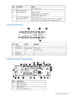
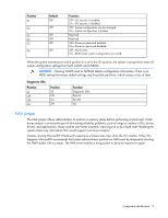
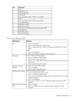
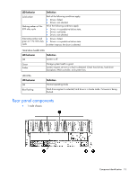
Item 5 6 7 8 9 10 11 12 13 14 15 16 17 18 19 20 21 22 23 24 25 26 27 28 Description Reserved connector SATA 1 connector SATA 2 connector Reserved connector System battery Reserved connector Internal USB connector Reserved connector System maintenance switch (SW1) System maintenance switch (SW4) LED power connector iLO connector NIC 1 connector (bottom) NIC 2 connector (top) USB/VGA connector Personality board connector TPM connector Processor socket 1 Processor 2 DIMM slots (6) SFF backplane power connector SATA connectors (2) Front panel USB/VGA connector VGA connector Front LED connector DIMM slots DIMM slots are numbered sequentially (1 through 6) for each processor. The supported AMP modes use the alpha assignments for population order, and the slot numbers designate the DIMM slot ID for spare replacement. System board switches System maintenance switch Component identification 8
-
 1
1 -
2
-
 3
3 -
 4
4 -
 5
5 -
 6
6 -
 7
7 -
 8
8 -
 9
9 -
 10
10 -
 11
11 -
 12
12 -
 13
13 -
14
-
15
-
16
-
17
-
18
-
19
-
20
-
21
-
22
-
23
-
24
-
25
-
26
-
27
-
28
-
29
-
30
-
31
-
32
-
33
-
34
-
35
-
36
-
37
-
38
-
39
-
40
-
41
-
42
-
43
-
44
-
45
-
46
-
47
-
48
-
49
-
50
-
51
-
52
-
53
-
54
-
55
-
56
-
57
-
58
-
59
-
60
-
61
-
62
-
63
-
64
-
65
-
66
-
67
-
68
-
69
-
70
-
71
-
72
-
73
-
74
-
75
-
76
-
77
-
78
-
79
-
80
-
81
-
82
 |
 |
