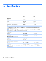
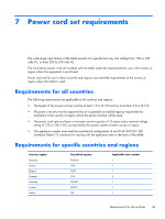
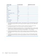
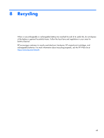
HP Slate 8 Pro 7600us HP Slate8 Pro Maintenance and Service Guide - Page 46
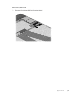
into the display panel assembly see, from the retention clip built
 |
View all HP Slate 8 Pro 7600us manuals
Add to My Manuals
Save this manual to your list of manuals |
Page 46 highlights
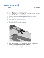
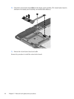
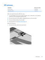
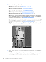
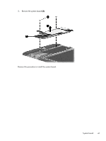
2. Disconnect the following cables from the system board: (1) WLAN main antenna cable (see WLAN antenna on page 23) (2) WLAN auxilliary antenna cable (see WLAN antenna on page 23) (3) Microphone ZIF cable and connector (see Microphone on page 27) (4) Rear-facing webcamera cable (see Rear-facing webcamera on page 29) (5) Front-facing webcamera cable (see Front-facing webcamera on page 31) (6) Power button board ZIF cable and connector, and detach the power button board cable (7) from the display panel assembly. (The power button board cable is attached to the display panel assembly with double-sided adhesive; see Power button board on page 32) (8) Volume button board ZIF cable and connector, and detach the volume button board cable (9) from the display panel assembly. (The volume button board cable is attached to the display panel assembly with double-sided adhesive; see Volume button board on page 35) (10) GPS antenna cable, and release the GPS antenna cable (11) from the retention clip built into the display panel assembly (see GPS antenna on page 25) 3. Remove the two Phillips PM1.5×2.5 screws (1) that secure the system board to the display panel assembly. 4. Detach the metal shielding (2) that secures the system board to the display panel assembly. (The metal shielding is attached to the display panel assembly with double-sided adhesive.) 40 Chapter 5 Removal and replacement procedures
-
 1
1 -
2
-
3
-
4
-
5
-
6
-
7
-
8
-
9
-
10
-
11
-
12
-
13
-
14
-
15
-
16
-
17
-
18
-
19
-
20
-
21
-
22
-
23
-
24
-
25
-
26
-
27
-
28
-
29
-
30
-
31
-
32
-
33
-
34
-
35
-
36
-
37
-
38
-
39
-
40
-
 41
41 -
 42
42 -
 43
43 -
 44
44 -
 45
45 -
 46
46 -
 47
47 -
 48
48 -
 49
49 -
 50
50 -
 51
51 -
52
-
53
 |
 |
