HP Spectre Pro x360 Maintenance and Service Guide - Page 37
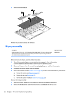
from the system board., Disconnect the speaker cables
 |
View all HP Spectre Pro x360 manuals
Add to My Manuals
Save this manual to your list of manuals |
Page 37 highlights
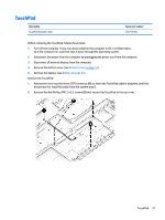
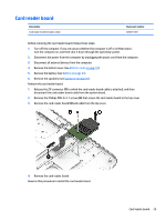
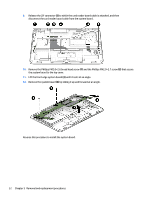
When replacing the system board, be sure that the following components are removed from the defective system board and installed on the replacement system board: ● WLAN module (see WLAN module on page 22) ● Solid-state drive (see Solid-state drive on page 24) ● Heat sink (see Heat sink on page 33) Remove the system board: 1. Release the ZIF connector (1) to which the audio jack cable is attached, and then disconnect the audio jack cable from the system board. 2. Disconnect the WLAN antenna cables (2) from the terminals on the WLAN module. NOTE: The WLAN antenna cable labeled "1" connects to the WLAN module "Main" terminal labeled "1". The WLAN antenna cable labeled "2" connects to the WLAN module "Aux" terminal labeled "2". 3. Release the ZIF connector (3) to which the display panel cable is attached, and then disconnect the display panel cable from the system board. 4. Disconnect the power connector cable (4) from the system board. 5. Disconnect the speaker cables (1) from the system board. 6. Release the ZIF connector (2) to which the keyboard backlight cable is attached, and then disconnect the keyboard backlight cable from the system board. 7. Release the ZIF connector (3) to which the keyboard cable is attached, and then disconnect the keyboard cable from the system board. 8. Release the ZIF connector (4) to which the TouchPad cable is attached, and then disconnect the TouchPad cable from the system board. System board 31
-
 1
1 -
2
-
3
-
4
-
5
-
6
-
7
-
8
-
9
-
10
-
11
-
12
-
13
-
14
-
15
-
16
-
17
-
18
-
19
-
20
-
21
-
22
-
23
-
24
-
25
-
26
-
27
-
28
-
29
-
30
-
31
-
 32
32 -
 33
33 -
 34
34 -
 35
35 -
 36
36 -
 37
37 -
 38
38 -
 39
39 -
 40
40 -
 41
41 -
 42
42 -
43
-
44
-
45
-
46
-
47
-
48
-
49
-
50
-
51
-
52
-
53
-
54
-
55
-
56
-
57
-
58
-
59
-
60
-
61
-
62
 |
 |