HP Spectre Pro x360 Maintenance and Service Guide - Page 45
Power connector cable, Remove the system board see
 |
View all HP Spectre Pro x360 manuals
Add to My Manuals
Save this manual to your list of manuals |
Page 45 highlights
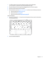
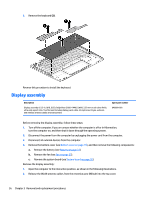
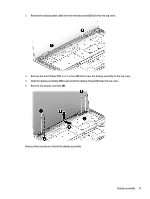
Power connector cable Description Power connector cable Spare part number 801513-001 Before removing the power connector cable, follow these steps: 1. Shut down the computer. If you are unsure whether the computer is off or in Hibernation, turn the computer on, and then shut it down through the operating system. 2. Disconnect all external devices connected to the computer. 3. Disconnect the power from the computer by first unplugging the power cord from the AC outlet and then unplugging the AC adapter from the computer. 4. Remove the bottom cover (see Bottom cover on page 19), and then remove the following components: a. Remove the battery (see Battery on page 21). b. Remove the fan (see Fan on page 25). c. Remove the system board (see System board on page 30). d. Remove the display assembly (see Display assembly on page 36). Remove the power connector cable: 1. Release the power connector cable (1) from the retention clips built into the bottom cover. 2. Remove the Phillips PM2.0×4.1 screw (2) that secures the power connector to the top cover. 3. Remove the power connector cable (3). Reverse this procedure to install the power connector cable. Power connector cable 39
-
 1
1 -
2
-
3
-
4
-
5
-
6
-
7
-
8
-
9
-
10
-
11
-
12
-
13
-
14
-
15
-
16
-
17
-
18
-
19
-
20
-
21
-
22
-
23
-
24
-
25
-
26
-
27
-
28
-
29
-
30
-
31
-
32
-
33
-
34
-
35
-
36
-
37
-
38
-
39
-
 40
40 -
 41
41 -
 42
42 -
 43
43 -
 44
44 -
 45
45 -
 46
46 -
 47
47 -
 48
48 -
 49
49 -
 50
50 -
51
-
52
-
53
-
54
-
55
-
56
-
57
-
58
-
59
-
60
-
61
-
62
 |
 |