HP Stream 11-aa000 Maintenance and Service Guide - Page 71
If it is necessary to replace the G-sensor module and G-sensor module cable
 |
View all HP Stream 11-aa000 manuals
Add to My Manuals
Save this manual to your list of manuals |
Page 71 highlights
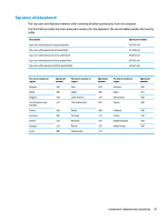
c. Release the TouchScreen board (2) by lifting the right side of the board and swinging it up and to the left. d. Release the adhesive support strip (1) that secures the TouchScreen board cable to the TouchScreen board. e. Disconnect the TouchScreen board cable (2) from the TouchScreen board. f. Remove the TouchScreen board cable. The TouchScreen board cable is available using spare part number 910163-001. 18. If it is necessary to replace the G-sensor module and G-sensor module cable: a. Remove the display panel assembly. b. Release the G-sensor module cable (1) from the gap between the display left hinge and the display back cover. c. Release the G-sensor module cable from the retention clips (2) and routing channel built into the display back cover. Component replacement procedures 63
-
 1
1 -
2
-
3
-
4
-
5
-
6
-
7
-
8
-
9
-
10
-
11
-
12
-
13
-
14
-
15
-
16
-
17
-
18
-
19
-
20
-
21
-
22
-
23
-
24
-
25
-
26
-
27
-
28
-
29
-
30
-
31
-
32
-
33
-
34
-
35
-
36
-
37
-
38
-
39
-
40
-
41
-
42
-
43
-
44
-
45
-
46
-
47
-
48
-
49
-
50
-
51
-
52
-
53
-
54
-
55
-
56
-
57
-
58
-
59
-
60
-
61
-
62
-
63
-
64
-
65
-
 66
66 -
 67
67 -
 68
68 -
 69
69 -
 70
70 -
 71
71 -
 72
72 -
 73
73 -
 74
74 -
 75
75 -
 76
76 -
77
-
78
-
79
-
80
-
81
-
82
-
83
-
84
-
85
-
86
-
87
-
88
-
89
-
90
-
91
-
92
-
93
-
94
-
95
 |
 |
