HP Stream 13-c000 Maintenance and Service Guide - Page 45
WLAN module, Remove the Phillips PM2.0×3.0 screw
 |
View all HP Stream 13-c000 manuals
Add to My Manuals
Save this manual to your list of manuals |
Page 45 highlights
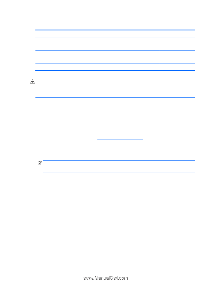
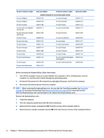
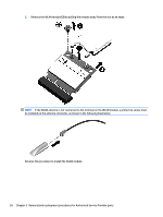
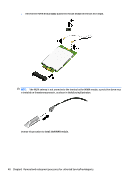
WLAN module Description Broadcom BCM43142 802.11 bgn 1x1 Wi-Fi + BT4.0 HMC Combo Adapter Realtek RT8723BE 802.11bgn 1x1 Wi-Fi + BT 4.0 Combo Adapter Intel Dual Band Wireless-AC 3160 802.11 ac 1×1 WiFi + Bluetooth 4.0 Combo Adapter Broadcom BCM43142 802.11 b/g/n 1x1 Wi-Fi + BT4.0 M.2 Combo Adapter Intel Dual Band Wireless-AC 3165 802.11 ac 1x1 WiFi + BT 4.0 Combo Adapter Spare part number 753076-005 753077-005 784638-005 792608-005 806723-005 CAUTION: To prevent an unresponsive system, replace the wireless module only with a wireless module authorized for use in the computer by the governmental agency that regulates wireless devices in your country or region. If you replace the module and then receive a warning message, remove the module to restore device functionality, and then contact technical support. Before removing the WLAN module, follow these steps: 1. Shut down the computer. If you are unsure whether the computer is off or in Hibernation, turn the computer on, and then shut it down through the operating system. 2. Disconnect all external devices connected to the computer. 3. Disconnect the power from the computer by first unplugging the power cord from the AC outlet and then unplugging the AC adapter from the computer. 4. Remove the keyboard/top cover (see Keyboard/top cover on page 29). Make sure the battery cable is disconnected from the system board. Remove the WLAN module: 1. Disconnect the WLAN antenna cables (1) from the terminal on the WLAN module. NOTE: The 1/black WLAN antenna cable is connected to the WLAN module 1/Main terminal. Either one or two antennas may be connected to the module. 2. Remove the Phillips PM2.0×3.0 screw (2) that secures the WLAN module to the computer. (The WLAN module tilts up.) Component replacement procedures 37
-
 1
1 -
2
-
3
-
4
-
5
-
6
-
7
-
8
-
9
-
10
-
11
-
12
-
13
-
14
-
15
-
16
-
17
-
18
-
19
-
20
-
21
-
22
-
23
-
24
-
25
-
26
-
27
-
28
-
29
-
30
-
31
-
32
-
33
-
34
-
35
-
36
-
37
-
38
-
39
-
 40
40 -
 41
41 -
 42
42 -
 43
43 -
 44
44 -
 45
45 -
 46
46 -
 47
47 -
 48
48 -
 49
49 -
 50
50 -
51
-
52
-
53
-
54
-
55
-
56
-
57
-
58
-
59
-
60
-
61
-
62
-
63
-
64
-
65
-
66
-
67
-
68
-
69
-
70
-
71
-
72
-
73
-
74
-
75
-
76
-
77
-
78
-
79
-
80
-
81
-
82
-
83
-
84
-
85
-
86
-
87
-
88
-
89
-
90
-
91
-
92
-
93
-
94
-
95
 |
 |