HP Vectra VEi8 HP Vectra VEi8, Technical Reference Manual (Product Description - Page 37
HP I/O Port Map I/O Addresses Used by the System
 |
View all HP Vectra VEi8 manuals
Add to My Manuals
Save this manual to your list of manuals |
Page 37 highlights
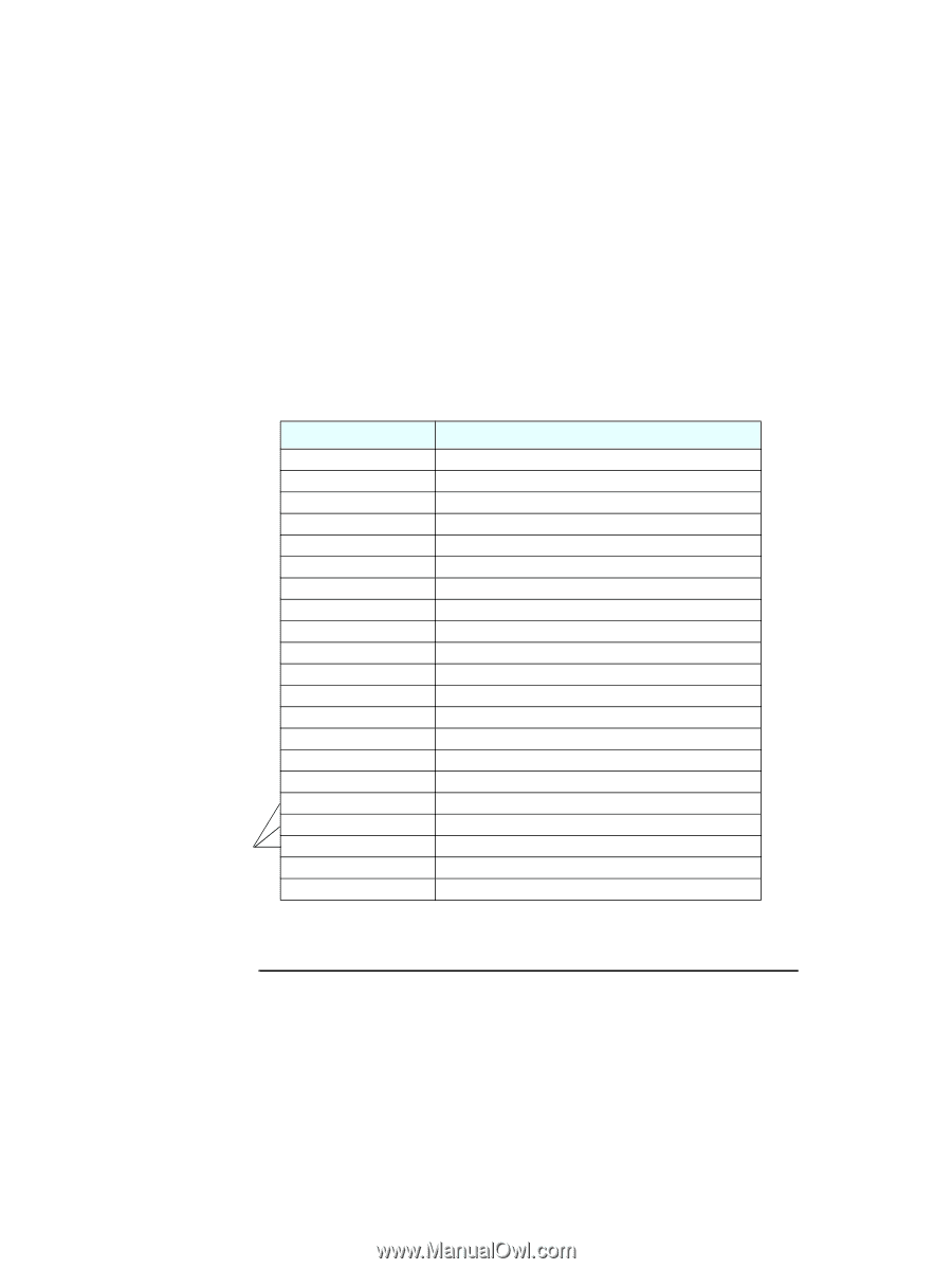
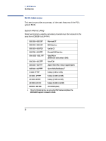
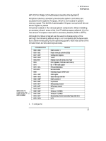
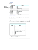
3 BIOS Overview BIOS Addresses HP I/O Port Map (I/O Addresses Used by the System1) Peripheral devices, accessory devices and system controllers are accessed via the system I/O space, which is not located in system memory space. The 64 KB of addressable I/O space comprises 8-bit and 16-bit registers (called I/O ports) located in the various system components. When installing an accessory board, ensure that the I/O address space selected is in the free area of the space reserved for accessory boards (100h to 3FFh). Although the Setup program can be used to change some of the settings, the following address map is not completely BIOS dependent, but is determined partly by the operating system. Note that some of the I/O addresses are allocated dynamically. Applies only if a supplementary ISA card is installed I/O Address Ports 0000 - 000F 0020 - 0021 0022 - 003F 0040 - 0043 0060, 0064 0061 0070 0070 - 0071 0072-0073 0080 0081 - 008F 00A0 - 00A1 00C0 - 00DF 00F0 - 00FF 0170 - 0177 01F0 - 01F7 0278 - 027F 02E8 - 02EF 02F8 - 02FF 0372 - 0377 0378 - 037A Function DMA controller 1 Master interrupt controller (8259) Configuration registers Timer 1 Keyboard controller (reset, slow A20) Port B (speaker, NMI status and control) Bit 7: NMI mask register RTC and CMOS data Extended CMOS Manufacturing port (POST card) DMA register Slave interrupt controller DMA controller 2 Co-processor IDE secondary channel IDE primary channel LPT 2 Serial port 4 (COM4) Serial port 2 (COM2) IDE secondary channel, secondary floppy disk drive LPT1 1. If configured. 37
-
 1
1 -
2
-
3
-
4
-
5
-
6
-
7
-
8
-
9
-
10
-
11
-
12
-
13
-
14
-
15
-
16
-
17
-
18
-
19
-
20
-
21
-
22
-
23
-
24
-
25
-
26
-
27
-
28
-
29
-
30
-
31
-
 32
32 -
 33
33 -
 34
34 -
 35
35 -
 36
36 -
 37
37 -
 38
38 -
 39
39 -
 40
40 -
 41
41 -
 42
42 -
43
-
44
 |
 |