HP Vectra XU 6/XXX HP Vectra VT 6/xxx, Familiarization guide - Page 18
Packaging
 |
View all HP Vectra XU 6/XXX manuals
Add to My Manuals
Save this manual to your list of manuals |
Page 18 highlights
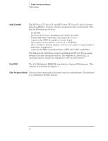
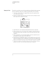
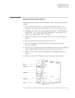
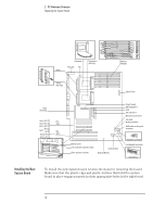
2 PC Hardware Structure Packaging Packaging This chapter covers the following servicing and installation topics: • replacing the system board • installing and replacing accessories: Ì installing and replacing a processor Ì installing and replacing main memory modules Ì installing video memory and other video modules Ì installing and replacing disk drives Ì installing and replacing accessory boards • replacing the power supply. Minitower Package The HP Vectra XU 6/xxx PC and HP Vectra VT 6/xxx PC are the second and third members of the HP Vectra family to use a minitower package (the HP Vectra VL 5/xx MT series 4 PC was the first). The locations of the main internal parts and external connectors of the HP Vectra XU/VT 6/xxx PC version of the minitower are shown in the diagrams on pages 2 and 4 of Chapter 1. All of the internal connectors appear on the system board, as can be seen on page 18, since there is no backplane in these PCs. Status Panel The status panel of the HP Vectra XU 6/xxx PC and HP Vectra VT 6/xxx PC have the following features: Ì a power on/off button with integrated on/error status light Ì a reset button Ì a hard disk activity light. Removing the Cover 1 For safety, remove all power leads, connections to networks, displays, and other peripheral equipment. 2 If necessary, unlock the cover at the back, using the key. 3 Lift the two securing latches at the front of the computer. 4 Hold the securing latches as shown in the next diagram. If necessary, push with your thumbs against the CD-ROM bezel. 5 Slide the cover forward until it is clear of the computer. 14
-
 1
1 -
2
-
3
-
4
-
5
-
6
-
7
-
8
-
9
-
10
-
11
-
12
-
 13
13 -
 14
14 -
 15
15 -
 16
16 -
 17
17 -
 18
18 -
 19
19 -
 20
20 -
 21
21 -
 22
22 -
 23
23 -
24
-
25
-
26
-
27
-
28
-
29
-
30
-
31
-
32
-
33
-
34
-
35
-
36
-
37
-
38
-
39
-
40
-
41
-
42
-
43
-
44
-
45
-
46
-
47
-
48
-
49
-
50
-
51
-
52
-
53
-
54
-
55
-
56
 |
 |