HP Vectra XU 6/XXX HP Vectra VT 6/xxx, Familiarization guide - Page 21
Replacing the System Board
 |
View all HP Vectra XU 6/XXX manuals
Add to My Manuals
Save this manual to your list of manuals |
Page 21 highlights
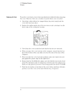
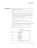
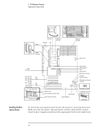
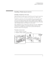
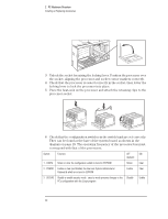
2 PC Hardware Structure Replacing the System Board Replacing the System Board The system board is shown on the next page. Take out the system board as follows: 1 Remove the PCI and ISA accessories from their slots. (There is no backplane: all internal slots and connectors are on the system board). 2 Disconnect all connectors (status panel, microphone, CD-ROM analog, multimedia control panel, wavetable, loudspeaker, external start, fan, SCSI, power supply, HDD, FDD, CD-ROM). 3 Push in the two buttons on the right bezel of the PC (see the diagram below). 4 Ease the system board towards the front of the PC. 5 There is a metal flap on the system board that must clear the I/O connector housing. 6 Ease the system board up and out through the top of the chassis, using the plastic ring-pull that is fastened to the top of the system board. 7 Make sure none of the plastic clips (shown in the diagram below) reengage. 8 Make sure none of the ISA slots catch in the mass media shelves. Button Plastic clip Plastic clip Plastic clip Button 17
-
 1
1 -
2
-
3
-
4
-
5
-
6
-
7
-
8
-
9
-
10
-
11
-
12
-
13
-
14
-
15
-
 16
16 -
 17
17 -
 18
18 -
 19
19 -
 20
20 -
 21
21 -
 22
22 -
 23
23 -
 24
24 -
 25
25 -
 26
26 -
27
-
28
-
29
-
30
-
31
-
32
-
33
-
34
-
35
-
36
-
37
-
38
-
39
-
40
-
41
-
42
-
43
-
44
-
45
-
46
-
47
-
48
-
49
-
50
-
51
-
52
-
53
-
54
-
55
-
56
 |
 |
