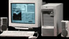
HP Vectra XU 6/XXX HP Vectra VT 6/xxx, Familiarization guide - Page 30
Installing or Replacing Accessory Boards
 |
View all HP Vectra XU 6/XXX manuals
Add to My Manuals
Save this manual to your list of manuals |
Page 30 highlights
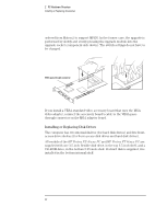
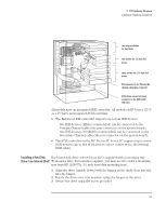
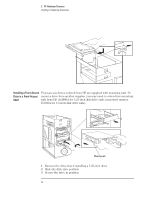
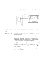
2 PC Hardware Structure Installing or Replacing Accessories Installing or Replacing Accessory Boards The location of the HP Vectra XU 6/xxx PC and HP Vectra VT 6/xxx PC accessory board slots is shown in the diagram on page 18. ISA boards should be installed in the lowest available slot, and PCI boards in the highest available slot, to ease cable routing. If you are installing a Creative Labs wavetable accessory board that operates with the integrated SoundBlaster audio interface, connect the board's interface cable to the wavetable interface connector on the system board (the location of which is shown in the diagram on page 18). If you loosened any screws on adjacent slots, during the installation of the new accessory, remember to tighten them again. If you have installed an ISA accessory board, you must run the Setup program and reserve the IRQ for the accessory board. PCI devices are then configured automatically. You should always leave at least one IRQ available for use by the integrated PCI devices. The Setup program can be used to select the level of support provided by the system BIOS for Plug and Play-compatible accessory boards. The procedures for doing this, and for configuring accessory boards under Windows 95, Windows 3.11 and other operating systems, are given in the User's Guide that is supplied with the computer. 26
-
 1
1 -
2
-
3
-
4
-
5
-
6
-
7
-
8
-
9
-
10
-
11
-
12
-
13
-
14
-
15
-
16
-
17
-
18
-
19
-
20
-
21
-
22
-
23
-
24
-
 25
25 -
 26
26 -
 27
27 -
 28
28 -
 29
29 -
 30
30 -
 31
31 -
 32
32 -
 33
33 -
 34
34 -
 35
35 -
36
-
37
-
38
-
39
-
40
-
41
-
42
-
43
-
44
-
45
-
46
-
47
-
48
-
49
-
50
-
51
-
52
-
53
-
54
-
55
-
56
 |
 |