HP Xw6400 HP xw6400 Workstation - Service and Technical Reference Guide - Page 154
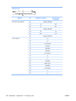
PCI or PCI Express Installation., Appendix C - Connector pins
 |
UPC - 882780645493
View all HP Xw6400 manuals
Add to My Manuals
Save this manual to your list of manuals |
Page 154 highlights
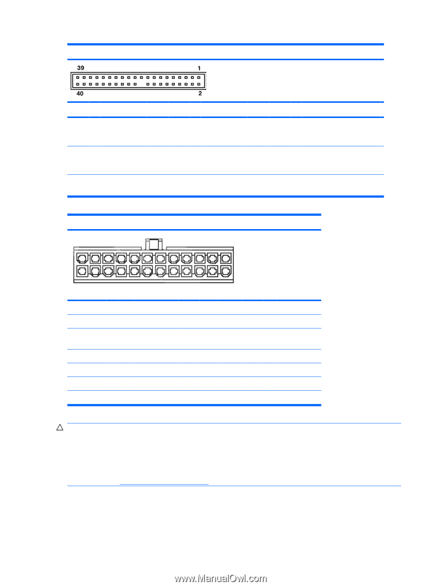
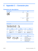
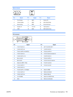
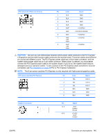
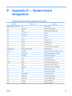
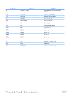
ATA/ATAPI (IDE) standard drive cable connector Pin 1 2 3 4 5 Signal Reset Ground DD7 DD8 DD6 6 7 8 9 10 DD9 DD5 DD10 DD4 DD11 11 12 13 14 DD3 DD12 DD2 DD13 Pin 15 16 17 18 19 20 21 22 23 24 25 26 27 28 Signal DD1 DD14 DD0 DD15 Ground (Key) DMARQ Ground DIOW Ground DIOR Ground IORDY CSEL Pin 29 30 31 32 33 34 35 36 37 38 39 40 Signal DMAK Ground INTRQ IOCS16 DA1 PDIAG (cable detect) DA0 DA2 CS1FX CS3FX DASP Ground 24-Pin Main power connector 13 24 1 1 +3.3 V 2 +3.3 V 3 GND 4 +5 V 5 GND 6 +5 V 7 GND 8 POK 9 +5 Vaux 10 +12 V-B 11 +12 V-A 12 +3.3 V 13 +3.3 V +3.3V-Rsense 12 14 -12 VL 15 GND 16 PS_O N_l 17 GND 18 GND 19 GND 20 GND 21 +5 V GND 22 +5 V and +5 V-Rsense 23 +5 V 24 GND CAUTION: Be sure you can differentiate between which power cable connects to the PCI Express x16 graphics card and which power cable connects to the system board. These two cables have different pin counts and different colors. The PCI Express power cable has a 6-pin black connector, and the system board power cable has an 8-pin white connector. When power is present, you must never connect the PCI Express power cable to the system board. If you do so, the system board may be damaged and your warranty voided. To see a picture of the PCI Express cable and where it must be connected, see PCI installation on page 79"PCI or PCI Express Installation." 144 Appendix C Appendix C - Connector pins ENWW
-
 1
1 -
2
-
3
-
4
-
5
-
6
-
7
-
8
-
9
-
10
-
11
-
12
-
13
-
14
-
15
-
16
-
17
-
18
-
19
-
20
-
21
-
22
-
23
-
24
-
25
-
26
-
27
-
28
-
29
-
30
-
31
-
32
-
33
-
34
-
35
-
36
-
37
-
38
-
39
-
40
-
41
-
42
-
43
-
44
-
45
-
46
-
47
-
48
-
49
-
50
-
51
-
52
-
53
-
54
-
55
-
56
-
57
-
58
-
59
-
60
-
61
-
62
-
63
-
64
-
65
-
66
-
67
-
68
-
69
-
70
-
71
-
72
-
73
-
74
-
75
-
76
-
77
-
78
-
79
-
80
-
81
-
82
-
83
-
84
-
85
-
86
-
87
-
88
-
89
-
90
-
91
-
92
-
93
-
94
-
95
-
96
-
97
-
98
-
99
-
100
-
101
-
102
-
103
-
104
-
105
-
106
-
107
-
108
-
109
-
110
-
111
-
112
-
113
-
114
-
115
-
116
-
117
-
118
-
119
-
120
-
121
-
122
-
123
-
124
-
125
-
126
-
127
-
128
-
129
-
130
-
131
-
132
-
133
-
134
-
135
-
136
-
137
-
138
-
139
-
140
-
141
-
142
-
143
-
144
-
145
-
146
-
147
-
148
-
 149
149 -
 150
150 -
 151
151 -
 152
152 -
 153
153 -
 154
154 -
 155
155 -
 156
156 -
 157
157 -
 158
158 -
 159
159 -
160
-
161
-
162
-
163
-
164
-
165
-
166
-
167
-
168
-
169
-
170
-
171
-
172
-
173
-
174
-
175
-
176
-
177
-
178
-
179
-
180
-
181
-
182
-
183
-
184
-
185
-
186
-
187
-
188
-
189
-
190
-
191
-
192
 |
 |