HP Xw6400 HP xw6400 Workstation - Service and Technical Reference Guide - Page 81
System fan assembly, Power supply, CAUTION
 |
UPC - 882780645493
View all HP Xw6400 manuals
Add to My Manuals
Save this manual to your list of manuals |
Page 81 highlights
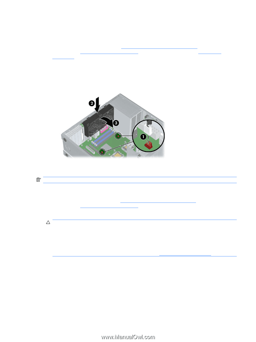
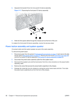
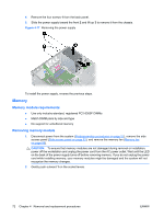
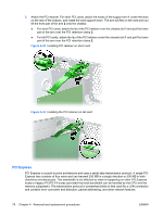
System fan assembly To remove the system fan assembly: 1. Disconnect power from the system (Predisassembly procedures on page 57), remove the side access panel (Side access panel on page 63), and remove the memory fan (Memory fan on page 69). 2. Disconnect the system fan cables from the system board connectors 1. 3. Press in on the ribbed release snap of the system fan housing 2, rotate the fan housing down 3, and lift the unit out of the chassis. Figure 4-16 Removing the system fan To replace a system fan assembly, there are four plastic tabs that must be aligned carefully in corresponding chassis holes and then rotate and snap. NOTE: Be sure to also reinstall the memory fan. Power supply 1. Disconnect power from the system (Predisassembly procedures on page 57) and remove the side access panel (Side access panel on page 63). 2. Disconnect the power supply cables from the system board. CAUTION: Be sure you can differentiate which power cable was disconnected from the PCI Express x16 graphics card and which power cable was disconnected from the system board. These two cables have different pin counts and different colors. The PCI Express power cable has a 6pin black connector, and the system board power cable has an 8-pin white connector. When power is present, you must never connect the PCI Express power cable to the system board. If you do so, the system board can be damaged and your warranty voided. To see a picture of the PCI Express cable and where it must be connected, see the PCI installation on page 79. 3. Disconnect all other components connected to the power supply, such as optical drives, diskette drive, hard drives, and select models of add-in cards. ENWW Removal and replacement of components 71
-
 1
1 -
2
-
3
-
4
-
5
-
6
-
7
-
8
-
9
-
10
-
11
-
12
-
13
-
14
-
15
-
16
-
17
-
18
-
19
-
20
-
21
-
22
-
23
-
24
-
25
-
26
-
27
-
28
-
29
-
30
-
31
-
32
-
33
-
34
-
35
-
36
-
37
-
38
-
39
-
40
-
41
-
42
-
43
-
44
-
45
-
46
-
47
-
48
-
49
-
50
-
51
-
52
-
53
-
54
-
55
-
56
-
57
-
58
-
59
-
60
-
61
-
62
-
63
-
64
-
65
-
66
-
67
-
68
-
69
-
70
-
71
-
72
-
73
-
74
-
75
-
 76
76 -
 77
77 -
 78
78 -
 79
79 -
 80
80 -
 81
81 -
 82
82 -
 83
83 -
 84
84 -
 85
85 -
 86
86 -
87
-
88
-
89
-
90
-
91
-
92
-
93
-
94
-
95
-
96
-
97
-
98
-
99
-
100
-
101
-
102
-
103
-
104
-
105
-
106
-
107
-
108
-
109
-
110
-
111
-
112
-
113
-
114
-
115
-
116
-
117
-
118
-
119
-
120
-
121
-
122
-
123
-
124
-
125
-
126
-
127
-
128
-
129
-
130
-
131
-
132
-
133
-
134
-
135
-
136
-
137
-
138
-
139
-
140
-
141
-
142
-
143
-
144
-
145
-
146
-
147
-
148
-
149
-
150
-
151
-
152
-
153
-
154
-
155
-
156
-
157
-
158
-
159
-
160
-
161
-
162
-
163
-
164
-
165
-
166
-
167
-
168
-
169
-
170
-
171
-
172
-
173
-
174
-
175
-
176
-
177
-
178
-
179
-
180
-
181
-
182
-
183
-
184
-
185
-
186
-
187
-
188
-
189
-
190
-
191
-
192
 |
 |