HP Xw6400 HP xw6400 Workstation - Service and Technical Reference Guide - Page 83
Installing memory module, CAUTION
 |
UPC - 882780645493
View all HP Xw6400 manuals
Add to My Manuals
Save this manual to your list of manuals |
Page 83 highlights
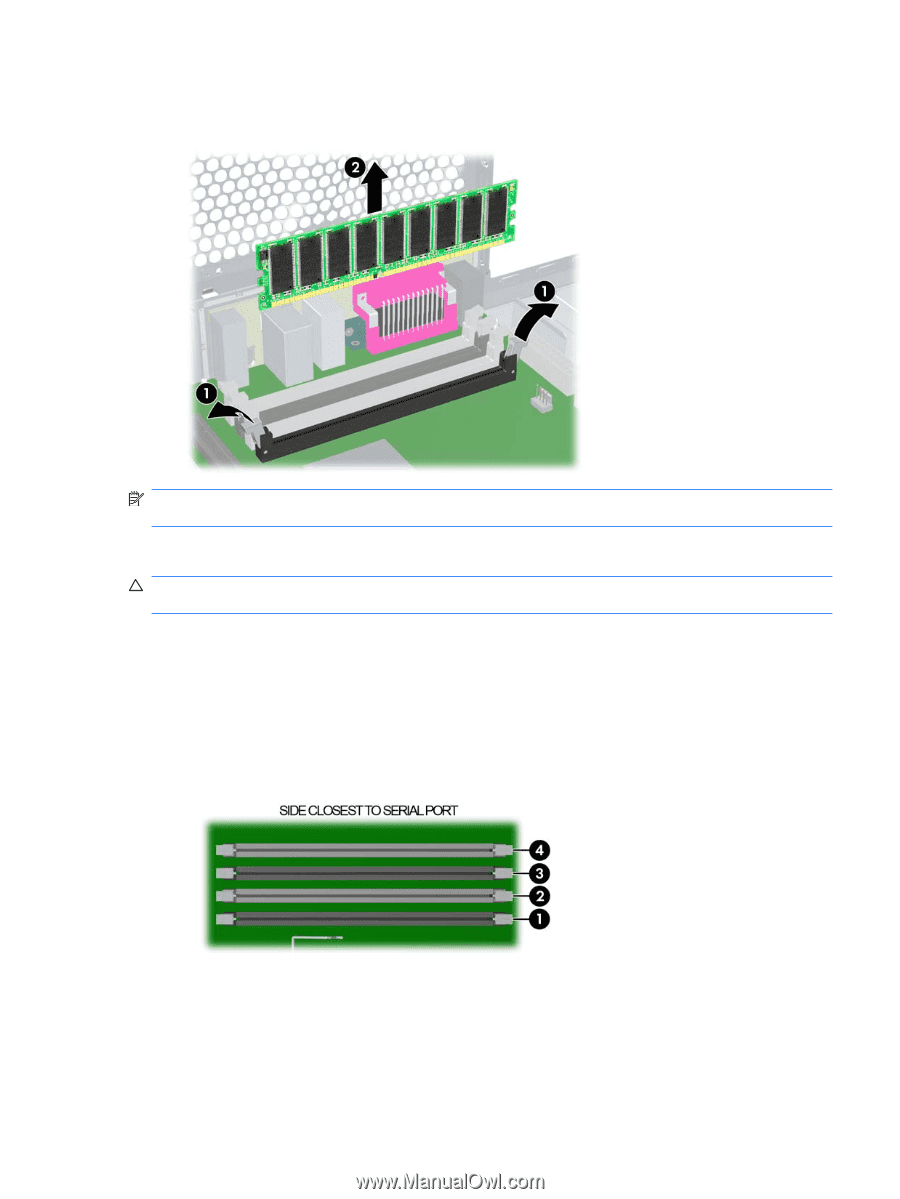
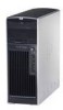
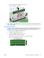
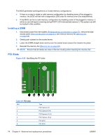
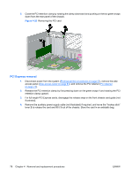
3. Lift the DIMM straight up 2 and remove it from the unit. Figure 4-18 Removing the DIMM NOTE: DIMMs and the DIMM sockets are keyed for proper installation. Be sure these guides line up when installing a DIMM. Installing memory module CAUTION: HP only ships DIMMs that are electrically and thermally compatible with this product. Thirdparty DIMMs might not be electrically or thermally compatible, so they are not supported by HP. You must load memory modules in valid configurations: ● If loading only one DIMM, install it in slot 1. ● If loading two DIMMs, install them in slots 1 and 3. ● If loading four DIMMs, install them in all slots. ● Load the memory module pairs in order of size, from smallest to largest. Figure 4-19 Identifying the memory slots ENWW Removal and replacement of components 73
-
 1
1 -
2
-
3
-
4
-
5
-
6
-
7
-
8
-
9
-
10
-
11
-
12
-
13
-
14
-
15
-
16
-
17
-
18
-
19
-
20
-
21
-
22
-
23
-
24
-
25
-
26
-
27
-
28
-
29
-
30
-
31
-
32
-
33
-
34
-
35
-
36
-
37
-
38
-
39
-
40
-
41
-
42
-
43
-
44
-
45
-
46
-
47
-
48
-
49
-
50
-
51
-
52
-
53
-
54
-
55
-
56
-
57
-
58
-
59
-
60
-
61
-
62
-
63
-
64
-
65
-
66
-
67
-
68
-
69
-
70
-
71
-
72
-
73
-
74
-
75
-
76
-
77
-
 78
78 -
 79
79 -
 80
80 -
 81
81 -
 82
82 -
 83
83 -
 84
84 -
 85
85 -
 86
86 -
 87
87 -
 88
88 -
89
-
90
-
91
-
92
-
93
-
94
-
95
-
96
-
97
-
98
-
99
-
100
-
101
-
102
-
103
-
104
-
105
-
106
-
107
-
108
-
109
-
110
-
111
-
112
-
113
-
114
-
115
-
116
-
117
-
118
-
119
-
120
-
121
-
122
-
123
-
124
-
125
-
126
-
127
-
128
-
129
-
130
-
131
-
132
-
133
-
134
-
135
-
136
-
137
-
138
-
139
-
140
-
141
-
142
-
143
-
144
-
145
-
146
-
147
-
148
-
149
-
150
-
151
-
152
-
153
-
154
-
155
-
156
-
157
-
158
-
159
-
160
-
161
-
162
-
163
-
164
-
165
-
166
-
167
-
168
-
169
-
170
-
171
-
172
-
173
-
174
-
175
-
176
-
177
-
178
-
179
-
180
-
181
-
182
-
183
-
184
-
185
-
186
-
187
-
188
-
189
-
190
-
191
-
192
 |
 |