HP j6700 hp workstation J6700 upgrade instructions (a6056-90000) - Page 7
Product Exploded Diagram
 |
View all HP j6700 manuals
Add to My Manuals
Save this manual to your list of manuals |
Page 7 highlights
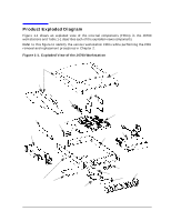
Getting Started Product Exploded Diagram Product Exploded Diagram Figure 1-1 shows an exploded view of the internal components (FRUs) in the J6700 workstations and Table 1-1 describes each of the exploded views components. Refer to this figure to identify the various workstation FRUs while performing the FRU removal and replacement procedures in Chapter 2. Figure 1-1. Exploded View of the J6700 Workstation Desk side only 16 9 10 3 6 15 8 1 2 12 Plastic cover desk side only 5 7 4 14 13 11 Chapter 1 7
-
 1
1 -
 2
2 -
 3
3 -
 4
4 -
 5
5 -
 6
6 -
 7
7 -
 8
8 -
 9
9 -
 10
10 -
 11
11 -
 12
12 -
13
-
14
-
15
-
16
-
17
-
18
-
19
-
20
-
21
-
22
-
23
-
24
-
25
-
26
 |
 |

Chapter 1
7
Getting Started
Product Exploded Diagram
Product Exploded Diagram
Figure 1-1 shows an exploded view of the internal components (FRUs) in the J6700
workstations and Table 1-1 describes each of the exploded views components.
Refer to this figure to identify the various workstation FRUs while performing the FRU
removal and replacement procedures in Chapter 2.
Figure 1-1.
Exploded View of the J6700 Workstation
15
16
3
8
1
6
9
2
12
10
5
4
11
7
13
14
Desk side only
Plastic cover
desk side only