HP j6700 hp workstation J6700 upgrade instructions (a6056-90000) - Page 8
Table 1-1. Description of the Components in the J6700 Exploded Diagram
 |
View all HP j6700 manuals
Add to My Manuals
Save this manual to your list of manuals |
Page 8 highlights
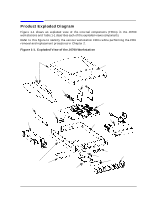
Getting Started Product Exploded Diagram Table 1-1. Description of the Components in the J6700 Exploded Diagram Numbers in Figure 1-1 Description 1 J6700 System Board Assembly 2 Power supply 500W includes system speaker, power supply fans, and LCD display cable 3 SDRAM DIMMs 4 LVD Ultra SCSI hard disk 5 CD ROM slim-line, ATAPI Assembly 6 PCA, SCA backplane (disk drive) 7 LCD/power switch assembly 8 VRM assembly 9 PCA-PCI backplane board 10 PCI cage assembly includes PCI tray fan 11 Disk drive bracket assembly 12 Main chassis assembly 14 Internal SCSI cable 13 Disk EMI cover assembly 14 Front bezel assembly 15 Cosmetic cover (without logo) 16 Deskside pedestal 8 Chapter 1
-
 1
1 -
2
-
 3
3 -
 4
4 -
 5
5 -
 6
6 -
 7
7 -
 8
8 -
 9
9 -
 10
10 -
 11
11 -
 12
12 -
 13
13 -
14
-
15
-
16
-
17
-
18
-
19
-
20
-
21
-
22
-
23
-
24
-
25
-
26
 |
 |

8
Chapter 1
Getting Started
Product Exploded Diagram
Table 1-1. Description of the Components in the J6700 Exploded Diagram
Numbers in Figure 1-1
Description
1
J6700 System Board Assembly
2
Power supply 500W includes system speaker,
power supply fans, and LCD display cable
3
SDRAM DIMMs
4
LVD Ultra SCSI hard disk
5
CD ROM slim-line, ATAPI Assembly
6
PCA, SCA backplane (disk drive)
7
LCD/power switch assembly
8
VRM assembly
9
PCA-PCI backplane board
10
PCI cage assembly includes PCI tray fan
11
Disk drive bracket assembly
12
Main chassis assembly
14
Internal SCSI cable
13
Disk EMI cover assembly
14
Front bezel assembly
15
Cosmetic cover (without logo)
16
Deskside pedestal