HP mt42 Maintenance and Service Guide - Page 42
WLAN/Bluetooth combo card
 |
View all HP mt42 manuals
Add to My Manuals
Save this manual to your list of manuals |
Page 42 highlights
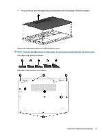
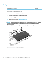
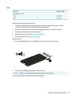
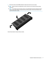
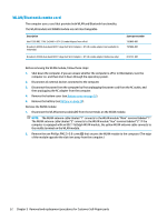
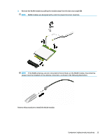
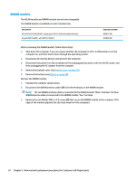
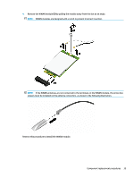
WLAN/Bluetooth combo card The computer uses a card that provides both WLAN and Bluetooth functionality. The WLAN module and WWAN module are not interchangeable. Description Intel 7265 802.11 AC 2x2 WiFi + BT 4.2 Combo Adapter (non-vPro) Broadcom 43228 dual-band 802.11abgn 2x2 Wi-Fi Adapter + BT 4.0 combo adapter (not available in Indonesia) Broadcom 43228 dual-band 802.11abgn 2x2 Wi-Fi Adapter + BT 4.0 combo adapter (Indonesia only) Spare part number 793840-001 797884-001 812132-001 Before removing the WLAN module, follow these steps: 1. Shut down the computer. If you are unsure whether the computer is off or in Hibernation, turn the computer on, and then shut it down through the operating system. 2. Disconnect all external devices connected to the computer. 3. Disconnect the power from the computer by first unplugging the power cord from the AC outlet, and then unplugging the AC adapter from the computer. 4. Remove the bottom cover (see Bottom cover on page 25). 5. Remove the battery (see Battery on page 28). Remove the WLAN module: 1. Disconnect the WLAN antenna cables (1) from the terminals on the WLAN module. NOTE: The WLAN antenna cable labeled "1" connects to the WLAN module "Main" terminal labeled "1". The WLAN antenna cable labeled "2" connects to the WLAN module "Aux" terminal labeled "2". If the computer is equipped with an 802.11a/b/g/n WLAN module, the yellow WLAN antenna cable connects to the middle terminal on the WLAN module. 2. Remove the one Phillips PM2.5×3.0 screw (2) that secures the WLAN module to the computer. (The edge of the module opposite the slot rises away from the computer.) 32 Chapter 5 Removal and replacement procedures for Customer Self-Repair parts
-
 1
1 -
2
-
3
-
4
-
5
-
6
-
7
-
8
-
9
-
10
-
11
-
12
-
13
-
14
-
15
-
16
-
17
-
18
-
19
-
20
-
21
-
22
-
23
-
24
-
25
-
26
-
27
-
28
-
29
-
30
-
31
-
32
-
33
-
34
-
35
-
36
-
 37
37 -
 38
38 -
 39
39 -
 40
40 -
 41
41 -
 42
42 -
 43
43 -
 44
44 -
 45
45 -
 46
46 -
 47
47 -
48
-
49
-
50
-
51
-
52
-
53
-
54
-
55
-
56
-
57
-
58
-
59
-
60
-
61
-
62
-
63
-
64
-
65
-
66
-
67
-
68
-
69
-
70
-
71
-
72
-
73
-
74
-
75
-
76
-
77
-
78
-
79
-
80
-
81
-
82
-
83
-
84
-
85
-
86
-
87
-
88
-
89
-
90
-
91
 |
 |
