HP vc4825T Troubleshooting Guide: HP vc4820T and vc4825T Thin Clients - Page 25
WARNING, CAUTION, General Hardware Installation Sequence, on Table
 |
View all HP vc4825T manuals
Add to My Manuals
Save this manual to your list of manuals |
Page 25 highlights
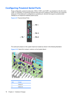
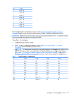
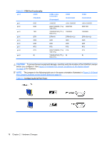
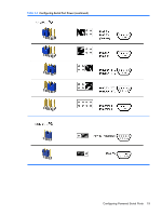
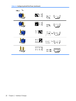
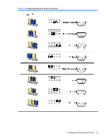
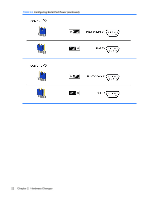
Item 3 4 5 6 7 8 9 10 Jumper COM2 JP3 COM2 JP2 COM3 JP1 COM3 JP2 COM3 JP3 COM4 JP1 COM4 JP2 COM4 JP3 Before beginning the configuration process, review General Hardware Installation Sequence on page 8 for procedures you should follow before and after installing or replacing hardware. WARNING! Before removing the side access panel, ensure that the thin client is turned off and the power cord is disconnected from the electrical outlet. To configure the serial ports: 1. Locate the serial port and jumper. 2. Place jumpers on the appropriate pins. (See Table 2-3 Configuring Serial Port Power on page 18 to determine the appropriate pins.) CAUTION: An unsupported configuration can cause severe equipment damage. Carefully verify COM Port Jumper locations and supported configurations before you configure a serial port. See Figure 2-10 Serial Port Jumper Locations on the System Board on page 16 and Table 2-3 Configuring Serial Port Power on page 18 for Jumper locations and supported configurations. Table 2-1 COM Port Default Configuration pin # COM1 COM2 COM3 COM4 pin 1 DCD +5V +5V +5V pin 2 RXD RXD RXD RXD pin 3 TXD TXD TXD TXD pin 4 DTR DTR DTR DTR pin 5 GND GND GND GND pin 6 DSR DSR DSR DSR pin 7 RTS RTS RTS RTS pin 8 CTS RXD (TTL) CTS CTS pin 9 RI TXD (TTL) RI RI Configuring Powered Serial Ports 17
-
 1
1 -
2
-
3
-
4
-
5
-
6
-
7
-
8
-
9
-
10
-
11
-
12
-
13
-
14
-
15
-
16
-
17
-
18
-
19
-
 20
20 -
 21
21 -
 22
22 -
 23
23 -
 24
24 -
 25
25 -
 26
26 -
 27
27 -
 28
28 -
 29
29 -
 30
30 -
31
-
32
-
33
-
34
-
35
-
36
-
37
-
38
-
39
-
40
-
41
-
42
-
43
-
44
-
45
-
46
-
47
-
48
-
49
-
50
-
51
-
52
-
53
-
54
-
55
-
56
-
57
-
58
-
59
-
60
-
61
-
62
-
63
-
64
-
65
-
66
-
67
-
68
-
69
-
70
-
71
-
72
-
73
-
74
-
75
-
76
-
77
-
78
 |
 |