Hitachi VB16Y Instruction Manual - Page 10
Functional Description - center roller
 |
UPC - 717709006256
View all Hitachi VB16Y manuals
Add to My Manuals
Save this manual to your list of manuals |
Page 10 highlights
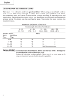
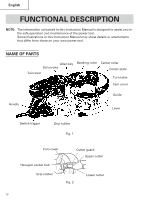
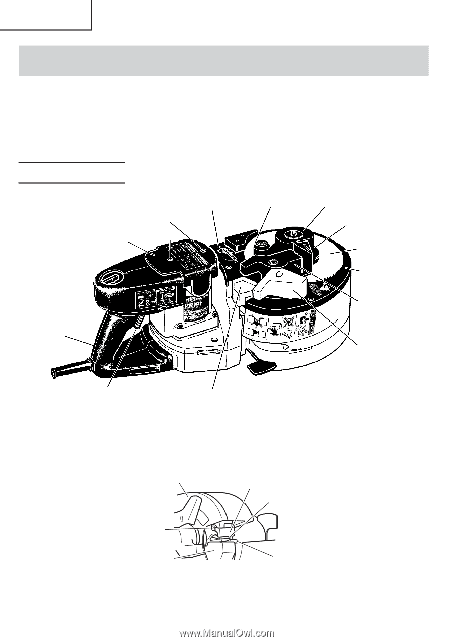
English FUNCTIONAL DESCRIPTION NOTE: The information contained in this Instruction Manual is designed to assist you in the safe operation and maintenance of the power tool. Some illustrations in this Instruction Manual may show details or attachments that differ from those on your own power tool. NAME OF PARTS Allen key Set screws Tail cover Bending roller Center roller Center plate Turn table Cam cover Handle Guide Lever Switch trigger Grip rubber Fig. 1 Cam cover Cutter guard Upper cutter Hexagon socket bolt Grip rubber Fig. 2 Lower cutter 10
-
 1
1 -
2
-
3
-
4
-
 5
5 -
 6
6 -
 7
7 -
 8
8 -
 9
9 -
 10
10 -
 11
11 -
 12
12 -
 13
13 -
 14
14 -
 15
15 -
16
-
17
-
18
-
19
-
20
-
21
-
22
-
23
-
24
-
25
-
26
-
27
-
28
-
29
-
30
-
31
-
32
-
33
-
34
-
35
-
36
-
37
-
38
-
39
-
40
-
41
-
42
-
43
-
44
-
45
-
46
-
47
-
48
-
49
-
50
-
51
-
52
-
53
-
54
-
55
-
56
-
57
-
58
-
59
-
60
-
61
-
62
-
63
-
64
-
65
-
66
-
67
-
68
 |
 |
English
10
Grip rubber
Fig. 1
Fig. 2
Lever
Switch trigger
Bending roller
Cutter guard
Upper cutter
Lower cutter
Set screws
Guide
Cam cover
Grip rubber
Allen key
Cam cover
Turn table
Hexagon socket bolt
Tail cover
Handle
Center plate
FUNCTIONAL DESCRIPTION
NOTE:
The information contained in this Instruction Manual is designed to assist you in
the safe operation and maintenance of the power tool.
Some illustrations in this Instruction Manual may show details or attachments
that differ from those on your own power tool.
NAME OF PARTS
Center roller