Hitachi VB16Y Instruction Manual - Page 17
Warning, How To Use Bending
 |
UPC - 717709006256
View all Hitachi VB16Y manuals
Add to My Manuals
Save this manual to your list of manuals |
Page 17 highlights
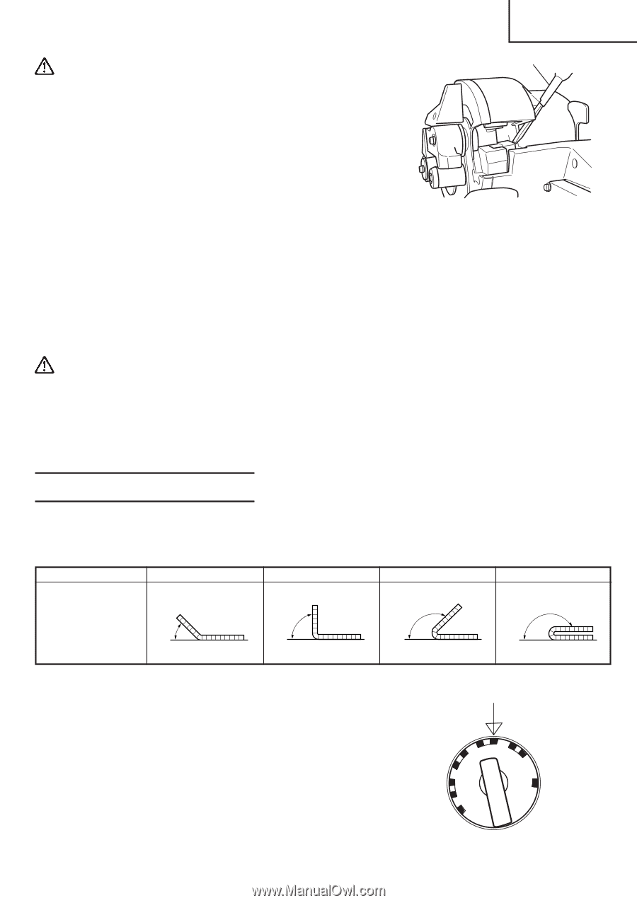
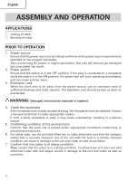
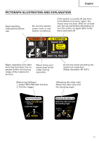
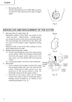
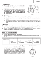
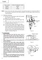
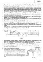
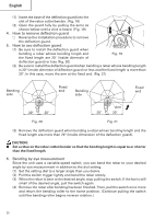
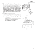
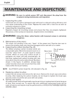
English WARNING: ⅜ To prevent accidents, always be sure to turn the switch OFF and unplug the power cord from the receptacle. ⅜ If you remove the hexagon socket bolt using the provided Allen key, you can remove the cutter. (Pushing the cutter guard up in the direction of the arrow shown in Fig. 10, facilitates removal of the upper cutter.) Fig. 11 4. Mounting (1) Get rid of dust around the cutter installing section and clean it up. (2) Align the hole of a new cutter and the position of a pin, and insert into the installing section. (3) Also replace the hexagon socket bolt (packed along with the cutter) with a new one simultaneously, completely tighten it using the attached Allen key, and then fix the cutter. CAUTION: G Install the cutter and accessories securely according to the instruction manual. If you fail to install them properly, they may come off and cause an injury. G Be sure to unplug the power cord from the receptacle when the cutter is checked, cleaned, and replaced. Failure to do so can result in a serious injury. HOW TO USE (BENDING) 1. Setting bending angles by setting dial The bar can be bent according to the angles indicated on the setting dial, as shown in Fig. 12. Dial indication 45° 90° 135° 180° Condition of rebar 45° 90° 135° 180° Fig. 12 In bending the rebar of #3(3/8"), #4(1/2"), and #5(5/ 8") diameters, a difference takes place in the bending angle even in the same dial position depending upon the difference of rebar's thickness. Slightly change a position of the setting dial depending upon the rebar's diameter even with the same bending angle as shown in Fig. 13. CUT180˚ 135˚ 0˚ RETURN Adjusting position 90˚ 45˚ Fig. 13 17
-
 1
1 -
2
-
3
-
4
-
5
-
6
-
7
-
8
-
9
-
10
-
11
-
 12
12 -
 13
13 -
 14
14 -
 15
15 -
 16
16 -
 17
17 -
 18
18 -
 19
19 -
 20
20 -
 21
21 -
 22
22 -
23
-
24
-
25
-
26
-
27
-
28
-
29
-
30
-
31
-
32
-
33
-
34
-
35
-
36
-
37
-
38
-
39
-
40
-
41
-
42
-
43
-
44
-
45
-
46
-
47
-
48
-
49
-
50
-
51
-
52
-
53
-
54
-
55
-
56
-
57
-
58
-
59
-
60
-
61
-
62
-
63
-
64
-
65
-
66
-
67
-
68
 |
 |