Hitachi VB16Y Instruction Manual - Page 20
How to remove deflection guard, How to use deflection guard, Bending by eye measurement - rebar cutter bender
 |
UPC - 717709006256
View all Hitachi VB16Y manuals
Add to My Manuals
Save this manual to your list of manuals |
Page 20 highlights
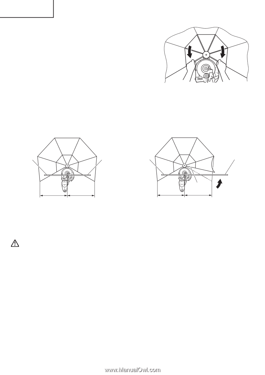
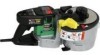
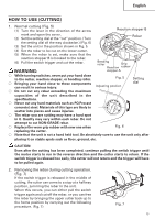
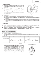
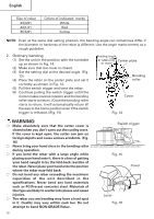
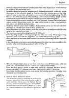
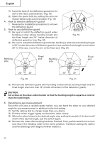
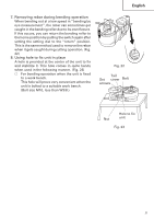
English (1) Insert the base of the deflection guard into the slot of the rebar cutter/bender. (Fig. 18) (2) Open the guard fully by pulling the arms as shown below until a click is heard. (Fig. 19) 4. How to remove deflection guard ⅜ Reverse the installation procedure to remove the deflection guard. 5. How to use deflection guard (1) Be sure to install the deflection guard when bending a rebar whose bending length and Fig. 19 the fixed length are 20" (inside dimensin of deflection guard) or less (Fig. 20) (2) Be sure to install the deflection guard when bending a rebar whose bending length is 20" (inside dimensin of diflection guard) or less and the fixed length is more than 20". In this case, move the arm at the fixed end. (Fig. 21) Bending side Fixed end Bending side Fixed end 20" 20" Arm 20" 20" Fig. 20 Fig. 21 (3) Remove the deflection guard when bending a rebar whose bending length and the fixed length are more than 20" (inside dimension of the deflection guard). CAUTION: G Set a rebar on the rebar cutter/bender so that the bending length is equal to or shorter than the fixed length. 6. Bending by eye measurement Since the unit uses a variable-speed switch, you can bend the rebar to your desired angle by eye measurement in addition to the dial setting. (1) Set the setting dial to a larger angle than you desire. (2) Pull the switch trigger lightly and bend the rebar slowly. (3) When the rebar is bent to the desired angle, stop pulling the switch. If the bar is still small of the desired angle, pull the switch again. (4) Remove the rebar after bending has been finished. Then, pull the switch once more and return the bending roller to the home position. (Continue pulling the switch until the bending roller begins reverse rotation.) 20
-
 1
1 -
2
-
3
-
4
-
5
-
6
-
7
-
8
-
9
-
10
-
11
-
12
-
13
-
14
-
 15
15 -
 16
16 -
 17
17 -
 18
18 -
 19
19 -
 20
20 -
 21
21 -
 22
22 -
 23
23 -
 24
24 -
 25
25 -
26
-
27
-
28
-
29
-
30
-
31
-
32
-
33
-
34
-
35
-
36
-
37
-
38
-
39
-
40
-
41
-
42
-
43
-
44
-
45
-
46
-
47
-
48
-
49
-
50
-
51
-
52
-
53
-
54
-
55
-
56
-
57
-
58
-
59
-
60
-
61
-
62
-
63
-
64
-
65
-
66
-
67
-
68
 |
 |