Honeywell TB7100A1000 Installation Instructions - Page 2
Caution - wiring
 |
View all Honeywell TB7100A1000 manuals
Add to My Manuals
Save this manual to your list of manuals |
Page 2 highlights
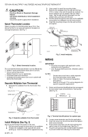
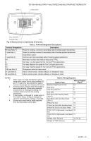
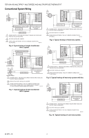
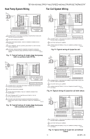
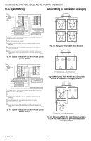
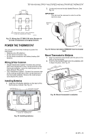
TB7100A1000 MULTIPRO™ MULTISPEED AND MULTIPURPOSE THERMOSTAT CAUTION Electrical Shock or Equipment Damage Hazard. Can shock individuals or short equipment circuitry. Disconnect power supply before installation. Select Thermostat Location Select a location for the thermostat about 5 ft (1.5m) above the floor in an area with good air circulation at average temperature. See Fig. 1. 3. Use a pencil to mark the mounting holes. 4. Remove the wallplate from the wall and drill two 3/16 in. holes in the wall (if drywall) as marked. For firmer material such as plaster, drill two 7/32 in. holes. Tap the wall anchors (provided) into the drilled holes until flush with the wall. 5. Pull the wires through the wire hole on the wallplate and position the wallplate over the wall anchors. 6. Insert the mounting screws into the wall anchors and tighten. DRILLED HOLES (2) WALL ANCHORS (2) YES NO NO NO 5 FEET [1.5 METERS] WALLPLATE M22268 MOUNTING SCREWS (2) Fig. 3. Install wallplate. M22258 Fig. 1. Select thermostat location. Do not install the thermostat where it can be affected by: - Drafts or dead spots behind doors and in corners. - Hot or cold air from ducts. - Radiant heat from sun or appliances. - Concealed pipes and chimneys. - Unheated (uncooled) areas such as an outside wall behind the thermostat. Separate Wallplate from Thermostat 1. Separate the wallplate from the thermostat. See Fig. 2. WALLPLATE WIRE HOLE WIRING IMPORTANT - All wiring must agree with applicable codes, ordinances and regulations. - Use 18 gauge thermostat wire. Shielded cable is not required. NOTES: - - - Sensor wires must have a cable separate from the thermostat control cable. Refer to Table 2 for terminal designation descriptions. See Fig. 6 through 17 for wiring diagrams for specific equipment applications. 1. Select set of terminal identifications that correspond to your system type (conventional or heat pump). (See Fig. 4). SCREW TERMINALS THERMOSTAT M22267 Fig. 2. Separate wallplate from thermostat. Install Wallplate (See Fig. 3) Mount the thermostat horizontally on the wall: 1. Pull the wires through the wire hole on the wallplate. 2. Position the wallplate on the wall with the arrow pointing up. Level the wallplate for appearance only. 62-0273-05 C W1 G G2 Y G3 O/B S1 RC S2 R M27415 Fig. 4. Terminal identifications for system type. 2. Loosen screw terminals used for the application. 3. Insert the wires into the terminal block and tighten each screw terminal. 4. Push excess wire back into the wall opening and restrict wires to the shaded area. See Fig. 5. 5. Plug the wall opening with nonflammable insulation to prevent drafts from affecting the thermostat. 2
-
 1
1 -
 2
2 -
 3
3 -
 4
4 -
 5
5 -
 6
6 -
 7
7 -
 8
8 -
9
-
10
-
11
-
12
-
13
-
14
-
15
-
16
 |
 |