Honeywell TB7100A1000 Installation Instructions - Page 3
Table 2. Terminal Designation Descriptions. - thermostat
 |
View all Honeywell TB7100A1000 manuals
Add to My Manuals
Save this manual to your list of manuals |
Page 3 highlights
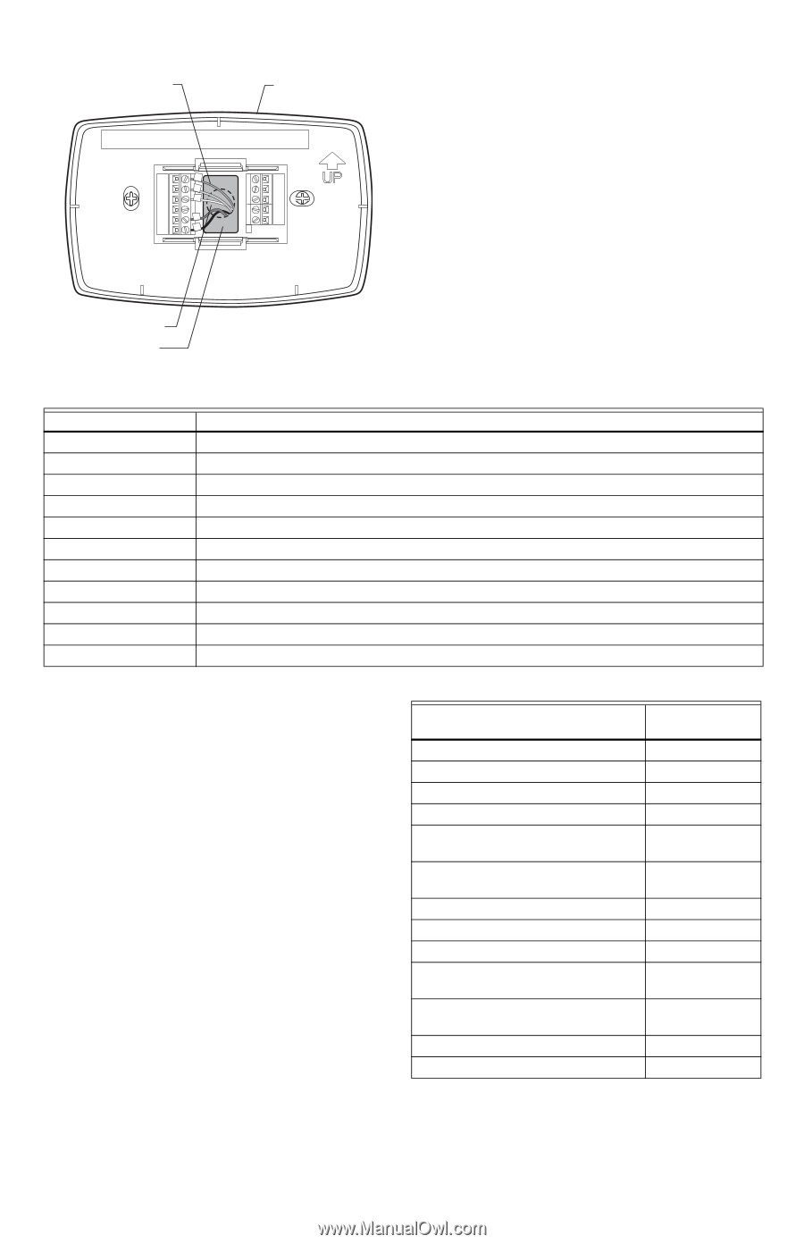
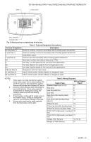
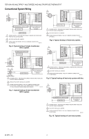
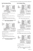
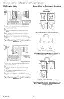
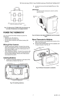
WIRE TB7100A1000 MULTIPRO™ MULTISPEED AND MULTIPURPOSE THERMOSTAT WALLPLATE WALL OPENING SHADED AREA M22266 Fig. 5. Restrict wires to shaded area of wire hole. Table 2. Terminal Designation Descriptions. Terminal Designation Description RC (see Note 1) Power for cooling-connect to secondary side of cooling system transformer. R (see Note 1) Power for heating-connect to secondary side of heating system transformer. Y Compressor output. C (see Note 2) Common wire from secondary side of cooling system transformer. W1 Heat relay. Auxiliary heat relay to heat pump, PTAC. G Fan relay. Low fan speed for Fan Coil and PTAC applications. G2 Fan relay. Medium fan speed for Fan Coil applications only. G3 Fan relay. High fan speed for Fan Coil and PTAC applications. O/B (see Note 3) Changeover valve for heat pumps. S1 (see Note 4) Indoor remote sensor, remote setback, or changeover input. S2 (see Note 4) Indoor remote sensor, remote setback, or changeover input. NOTES: 1. 2. 3. 4. When used in a single-transformer system, leave metal jumper wire in place between RC and R. If used on a two-transformer system, remove metal jumper wire between RC and R. Common wire is optional when thermostat is used with batteries. When using separate transformers for heating and cooling, the common must come from the cooling transformer. If thermostat is configured for a heat pump in the Installer Setup, configure changeover valve for cool (O-factory setting) or heat (B). Sensor wires must have a cable separate from the thermostat control cable. Table 3. Wiring Diagrams. System Type Wiring Diagram Figure Standard Heat/Cool (1H/1C) 6, 7 Heat Only 8 Heat Only with Fan 9 Cool only 10 Heat Pump (No Auxiliary Heat) 11 (1H/1C) Heat Pump (with Auxiliary Heat) 12 (2H/1C) 4 Pipe Fan Coil 13 2 Pipe Fan Coil (with Auxiliary Heat) 14 2 Pipe Fan Coil (no Auxiliary Heat) 15 PTAC 1H/1C (High speed, Low speed 16 fan) PTAC 2H/1C (High speed, Low speed 17 fan) Multiple TR21 Sensors 18, 19, 20 Multiple C7189U Sensors 21 3 62-0273-05
-
 1
1 -
 2
2 -
 3
3 -
 4
4 -
 5
5 -
 6
6 -
 7
7 -
 8
8 -
 9
9 -
10
-
11
-
12
-
13
-
14
-
15
-
16
 |
 |