Honeywell TB7100A1000 Installation Instructions - Page 7
Power The Thermostat
 |
View all Honeywell TB7100A1000 manuals
Add to My Manuals
Save this manual to your list of manuals |
Page 7 highlights
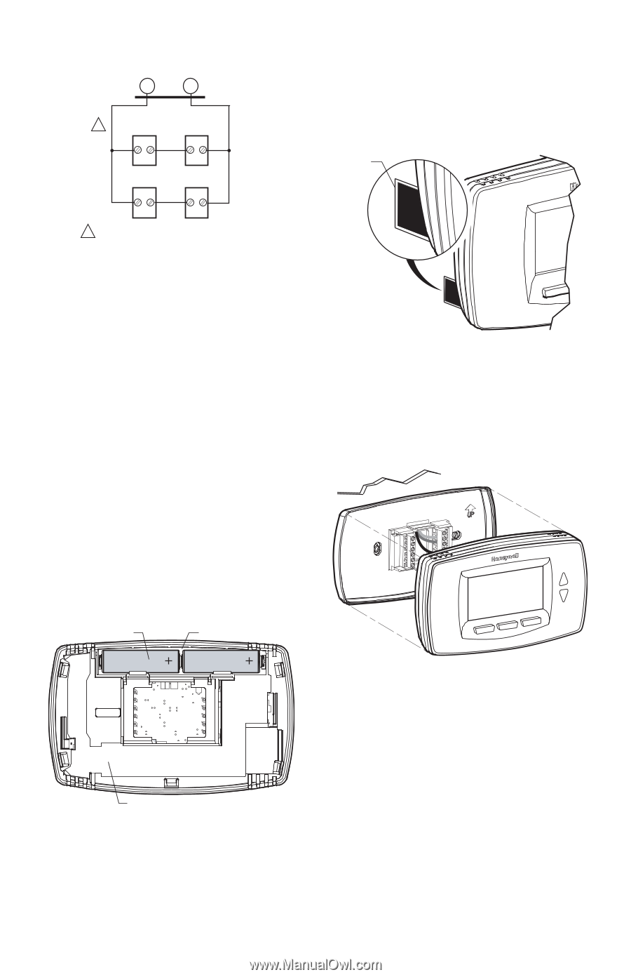
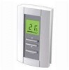
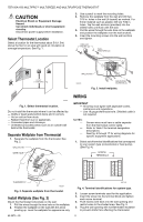
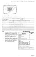
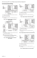
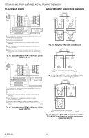
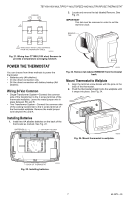
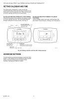
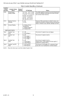
TB7100A1000 MULTIPRO™ MULTISPEED AND MULTIPURPOSE THERMOSTAT SUBBASE S1 S2 1 C7189 C7189 2. Locate and remove the tab labeled Remove. See Fig. 23. IMPORTANT This tab must be removed in order to set the real-time clock. C7189 C7189 REMOVE TAB REMOVE DURING INSTALLATION 1 WIRES MUST HAVE A CABLE SEPARATE FROM THE THERMOSTAT CABLE. M27432 Fig. 21. Wiring four C7189U (10K ohm) Sensors to provide a temperature averaging network. REMOVE DURING INSTALLATION POWER THE THERMOSTAT You can choose from three methods to power the thermostat: • Batteries only (AA alkaline). • 24 Vac direct connection only. • 24 Vac direct connection with battery backup (AA alkaline). Wiring 24 Vac Common • Single-Transformer System-Connect the common side of the transformer to the C screw terminal of the thermostat wallplate. Leave the metal jumper wire in place between RC and R. • Two-Transformer System-Connect the common side of the cooling transformer to the C screw terminal of the thermostat wallplate. Remove the metal jumper wire between RC and R. M22260 Fig. 23. Remove tab labeled REMOVE from thermostat back. Mount Thermostat to Wallplate 1. Align the terminal screw blocks with the pins on the back of the thermostat. 2. Push the thermostat straight onto the wallplate until it snaps into place. See Fig. 24. WALL Installing Batteries 1. Install two AA alkaline batteries on the back of the thermostat as marked. See Fig. 22. BATTERIES (2) BATTERY HOLDER M23024 Fig. 24. Mount thermostat to wallplate. BACK OF THERMOSTAT Fig. 22. Installing batteries. M22259 7 62-0273-05
-
 1
1 -
 2
2 -
 3
3 -
 4
4 -
 5
5 -
 6
6 -
 7
7 -
 8
8 -
 9
9 -
 10
10 -
 11
11 -
 12
12 -
13
-
14
-
15
-
16
 |
 |