Honeywell TB7100A1000 Installation Instructions - Page 9
Installer Setup Numbers, Settings, And Tests Table 4
 |
View all Honeywell TB7100A1000 manuals
Add to My Manuals
Save this manual to your list of manuals |
Page 9 highlights
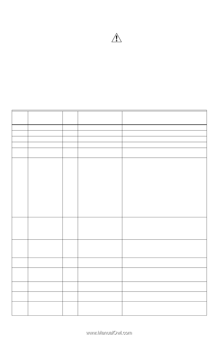
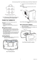
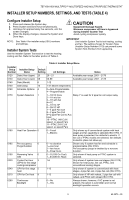
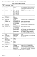
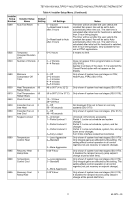
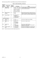
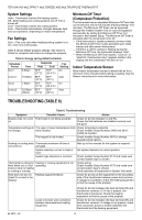
TB7100A1000 MULTIPRO™ MULTISPEED AND MULTIPURPOSE THERMOSTAT INSTALLER SETUP NUMBERS, SETTINGS, AND TESTS (TABLE 4) Configure Installer Setup 1. Press and release the System key. 2. Press System and Done keys simultaneously. 3. Hold keys for approximately five seconds, until the screen changes. 4. When the display changes, release the System and Done keys. NOTE: See Table 4 for installer setup (ISU) numbers and settings. Installer System Tests Use the Installer System Test section to test the heating, cooling and fan. Refer to the latter portion of Table 4. CAUTION Equipment Damage Hazard. Minimum compressor off time is bypassed during Installer System Test Avoid cycling compressor quickly. IMPORTANT Use Installer System Test to test heating, cooling and fan. The setting chosen for System Type (Installer Setup Number 0170) can prevent some System Test Numbers from appearing. Table 4. Installer Setup Menu. Installer Setup Number Installer Setup Name Default Setting All Settings Notes 0120 Date (Year Upper) 20 20-21 Available year range: 2001 - 2178 0130 Date (Year Lower) 08 00-99 Available year range: 2001 - 2178 0140 Date (Month) 6 1-12 0150 Date (Day) 15 1-31 (Month Dependent) 0160 Schedule Options 4 0-Non-Programmable 4-Programmable 0170 System Selection 1 1-1H/1C Conv Relay Y is used for 2 pipe fan coil output relay. 2-1H w/o fan 3-1H with fan 4-1C 5-1H/1C HP 6-2H/1C HP 7-4 pipe Fan Coil 8-2 pipe Fan Coil 9-2 pipe Fan Coil w/ Aux Heat 10-PTAC 1H/1C (Hi speed, Lo speed Fan) 11-PTAC 2H/1C (Hi speed, Lo speed Fan) 0180 Heat Fan Operation 0 0-Fossil 1-Electric Only shows up if conventional system with heat stages and fan capability is selected (ISU 0170). If heat pump is selected, fan defaults to electric. If fan coil or PTAC modes are selected, fan defaults to electric (does not show up). 0185 Pre-occupancy 0 Purge Duration 0-no duration 1-one hour 2-two hours 3-three hours Shown only if system has fan and schedule is programmable (ISU 0160). Pre-occupancy purge is enabled by a nonzero duration. 0190 Reversing Valve 0 O/B 0-O (O/B On Cool) 1-B (O/B On Heat) Only shown if heat pump or PTAC system is selected. 0220 Cycles Per Hour 3 1-6 (CPH) for first stage cooling/compressor Only shown if system has cool stages (ISU 0170). Shown for heat pump, fan coil, PTAC, and conventional cooling stages. 0240 CPH for first stage 5 heat 1-12 Only shown if system is conventional with heat stages, 4 pipe fan coil, 2 pipe fan coil (ISU 0170). 0270 CPH for Em Heat 9 1-12 Only shown if HP with reheat, 2 pipe fan coil with reheat, and PTAC with reheat (ISU 0170). 0280 Continuous Backlight 0 0-No 1-Yes Always shown; however, if AC power is not present, the option is overridden and normal backlight operation occurs. 9 62-0273-05
-
 1
1 -
2
-
3
-
 4
4 -
 5
5 -
 6
6 -
 7
7 -
 8
8 -
 9
9 -
 10
10 -
 11
11 -
 12
12 -
 13
13 -
 14
14 -
15
-
16
 |
 |