Husqvarna AUTOMOWER 450XH Owner Manual - Page 21
To install the boundary wire, 4.3 To install the guide wire
 |
View all Husqvarna AUTOMOWER 450XH manuals
Add to My Manuals
Save this manual to your list of manuals |
Page 21 highlights
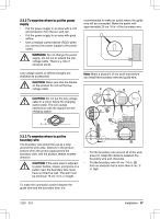
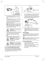
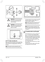
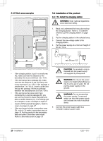
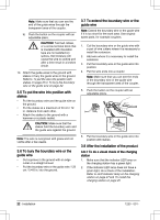
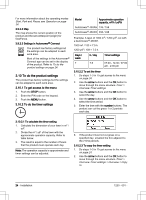
WARNING: Applicable to USA/ Canada. If power supply is installed outdoors: Risk of Electric Shock. Install only to a covered Class A GFCI receptacle (RCD) that has an enclosure that is weatherproof with the attachment plug cap inserted or removed. 6. Put the low-voltage cable in the ground with stakes or bury the cable. Refer to To put the wire into position with stakes on page 22 or To bury the boundary wire or the guide wire on page 22. 7. Connect the wires to the charging station. Refer to To install the boundary wire on page 21 and To install the guide wire on page 21. 8. Attach the charging station to the ground with the supplied screws. CAUTION: Do not make new holes in the charging station plate. CAUTION: Do not put your feet on the charging station. 3.4.2 To install the boundary wire 1. Put the boundary wire around all of the work area. Start and complete the installation behind the charging station. CAUTION: Do not put unwanted wire in a coil. The coil causes interference with the product. 5. Put the right end of boundary wire into the channel with the mark "AR". 6. Put the left end of boundary wire into the channel with the mark "AL". 7. Push the right connector onto the metal pin on the charging station with the mark "AR". 8. Push the left connector onto the metal pin on the charging station with the mark "AL". 9. Put the cable mark on the left and right boundary wire. 3.4.3 To install the guide wire 1. Open the connector and put the wires in the connector. 2. Close the connector with a pair of pliers. 3. Cut the guide wires 1-2 cm / 0.4-0.8 in. above each connector. 4. Put the guide wires centrally below the charging station plate, and push them through the slot in the charging station tower. 5. Push the connector onto the metal pin on the charging station with the mark "G1" (if applicable, also for G2 and G3). 6. Put the cable mark on the guide wires. 7. Put the end of the guide wires at the eyelet on the boundary wire. 8. Cut the boundary wire with a pair of wire cutters. 9. Connect the guide wires to the boundary wire with a coupler. 2. Open the connector and put the boundary wire in the connector. 3. Close the connector with a pair of pliers. 4. Cut the boundary wire 1-2 cm / 0.4-0.8 in. above each connector. 1230 - 001 - a) Put the 2 ends of the boundary wire and the end of the guide wires into the coupler. Installation - 21
-
 1
1 -
2
-
3
-
4
-
5
-
6
-
7
-
8
-
9
-
10
-
11
-
12
-
13
-
14
-
15
-
 16
16 -
 17
17 -
 18
18 -
 19
19 -
 20
20 -
 21
21 -
 22
22 -
 23
23 -
 24
24 -
 25
25 -
 26
26 -
27
-
28
-
29
-
30
-
31
-
32
-
33
-
34
-
35
-
36
-
37
-
38
-
39
-
40
-
41
-
42
-
43
-
44
-
45
-
46
-
47
-
48
-
49
-
50
-
51
-
52
-
53
-
54
-
55
-
56
-
57
-
58
-
59
-
60
 |
 |
