Husqvarna AUTOMOWER 450XH Owner Manual - Page 22
guide wire
 |
View all Husqvarna AUTOMOWER 450XH manuals
Add to My Manuals
Save this manual to your list of manuals |
Page 22 highlights
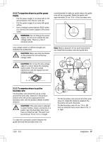
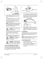
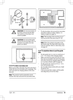
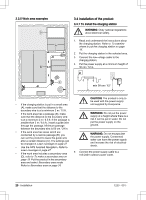
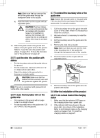
Note: Make sure that you can see the end of the guide wires through the transparent area of the coupler. b) Push the button on the coupler with an adjustable pliers. CAUTION: Twinned cables, or a screw terminal block that is insulated with insulation tape are not satisfactory splices. Soil moisture will cause the wire to oxidize and after a time result in a broken circuit. 10. Attach the guide wires to the ground with stakes or bury the guide wires in the ground. Refer to To put the wire into position with stakes on page 22 or To bury the boundary wire or the guide wire on page 22. 3.5 To put the wire into position with stakes • Put the boundary wire and the guide wire on the ground. • Put the stakes at a maximum of 30 cm / 12 in. distance from each other. • Attach the stakes to the ground with a hammer or a plastic mallet. CAUTION: Make sure that the stakes hold the boundary wire and the guide wire against the ground. Note: The wire is overgrown with grass and not visible after a few weeks. 3.6 To bury the boundary wire or the guide wire • Cut a groove in the ground with an edge cutter or a straight shovel. • Put the boundary wire or the guide wire 1-20 cm / 0.4-8 in. into the ground. 3.7 To extend the boundary wire or the guide wire Note: Extend the boundary wire or the guide wire if it is too short for the work area. Use original spare parts, for example couplers. 1. Cut the boundary wire or the guide wire with a pair of wire cutters where it is necessary to install the extension. 2. Add wire where it is necessary to install the extension. 3. Put the boundary wire or the guide wire into position. 4. Put the wire ends into a coupler. Note: Make sure that you can see the ends of the boundary wire or the guide wire through the transparent area of the coupler. 5. Push the button on the coupler with an adjustable pliers. 6. Put the boundary wire or the guide wire into position with stakes. 3.8 After the installation of the product 3.8.1 To do a visual check of the charging station 1. Make sure that the indicator LED lamp on the charging station has a green light. 2. If the indicator LED lamp does not have a green light, do a check of the installation. Refer to LED indicator lamp on the charging station on page 47 and To install the charging station on page 20. 22 - Installation 1230 - 001 -
-
 1
1 -
2
-
3
-
4
-
5
-
6
-
7
-
8
-
9
-
10
-
11
-
12
-
13
-
14
-
15
-
16
-
 17
17 -
 18
18 -
 19
19 -
 20
20 -
 21
21 -
 22
22 -
 23
23 -
 24
24 -
 25
25 -
 26
26 -
 27
27 -
28
-
29
-
30
-
31
-
32
-
33
-
34
-
35
-
36
-
37
-
38
-
39
-
40
-
41
-
42
-
43
-
44
-
45
-
46
-
47
-
48
-
49
-
50
-
51
-
52
-
53
-
54
-
55
-
56
-
57
-
58
-
59
-
60
 |
 |
