IBM 88632SU User Manual - Page 20
Server, controls, connectors, power, Front
 |
View all IBM 88632SU manuals
Add to My Manuals
Save this manual to your list of manuals |
Page 20 highlights
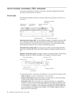
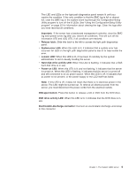
Server controls, connectors, LEDs, and power This section describes the controls, connectors, and light-emitting diodes (LEDs) and how to turn the server on and off. Front view The following illustration shows the controls, LEDs, and connectors on the front of the server. Hard disk drive status LED Hard disk drive activity LED Electrostatic-discharge connector Operator information panel DVD-eject button DVD drive activity LED Hard disk drive status LED: If a ServeRAID-8i adapter is installed, when this LED is lit it indicates that the associated hard disk drive has failed. If the LED flashes slowly (one flash per second), the drive is being rebuilt. If the LED flashes rapidly (three flashes per second), the controller is identifying the drive. Hard disk drive activity LED: On some server models, each hot-swap hard disk drive has an activity LED. When this LED is flashing, it indicates that the drive is in use. Operator information panel: This panel contains controls and LEDs. The following illustration shows the controls and LEDs on the operator information panel. Power-control button Information LED USB connector Release latch Power-on LED Hard disk drive activity LED Locator LED System-error LED The following controls, connectors, and LEDs are on the operator information panel: v USB connector: Connect a USB device to this connector. v Power-control button: Press this button to turn the server on and off manually. A power-control-button shield comes with the server. v Information LED: When this LED is lit, it indicates that there is a suboptimal condition in the server and that light path diagnostics will light an additional LED to help isolate the condition. If the LOG LED on the light path diagnostics panel is lit, information is available in the baseboard management controller (BMC) log or in the system-event log about the condition. The condition might be that the BMC log is full or almost full. 8 IBM System x3850 Type 8864: User's Guide
-
 1
1 -
2
-
3
-
4
-
5
-
6
-
7
-
8
-
9
-
10
-
11
-
12
-
13
-
14
-
 15
15 -
 16
16 -
 17
17 -
 18
18 -
 19
19 -
 20
20 -
 21
21 -
 22
22 -
 23
23 -
 24
24 -
 25
25 -
26
-
27
-
28
-
29
-
30
-
31
-
32
-
33
-
34
-
35
-
36
-
37
-
38
-
39
-
40
-
41
-
42
-
43
-
44
-
45
-
46
-
47
-
48
-
49
-
50
-
51
-
52
-
53
-
54
-
55
-
56
-
57
-
58
-
59
-
60
-
61
-
62
-
63
-
64
-
65
-
66
-
67
-
68
-
69
-
70
-
71
-
72
-
73
-
74
-
75
-
76
-
77
-
78
-
79
-
80
-
81
-
82
-
83
-
84
-
85
-
86
-
87
-
88
-
89
-
90
-
91
-
92
-
93
-
94
-
95
-
96
-
97
-
98
-
99
-
100
 |
 |
