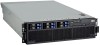
IBM 88632SU User Manual - Page 28
board, internal, connectors, jumpers
 |
View all IBM 88632SU manuals
Add to My Manuals
Save this manual to your list of manuals |
Page 28 highlights
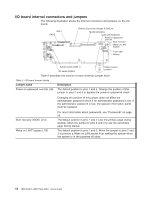
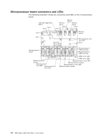
I/O board internal connectors and jumpers The following illustration shows the internal connectors and jumpers on the I/O board. SAS 1 SAS 2 Remote Supervisor Adapter II SlimLine Media backplane Light path diagnostic Power-on password override Boot recovery Wake-on-LAN bypass Front USB Battery System serial (COM 1) SP serial (COM 2) 123 Default jumper 1 2 3 position 123 Table 2 describes the function of each three-pin jumper block. Table 2. I/O board jumper blocks Jumper name Description Power-on password override (J9) The default position is pins 1 and 2. Change the position of this jumper to pins 2 and 3 to bypass the power-on password check. Changing the position of this jumper does not affect the administrator password check if an administrator password is set. If the administrator password is lost, the operator information panel must be replaced. Boot recovery (BIOS) (J14) Wake on LAN® bypass (J15) For more information about passwords, see "Passwords" on page 55. The default position is pins 1 and 2 (use the primary page during startup). Move the jumper to pins 2 and 3 to use the secondary page during startup. The default position is pins 1 and 2. Move the jumper to pins 2 and 3 to prevent a Wake on LAN packet from waking the system when the system is in the powered-off state. 16 IBM System x3850 Type 8864: User's Guide
-
 1
1 -
2
-
3
-
4
-
5
-
6
-
7
-
8
-
9
-
10
-
11
-
12
-
13
-
14
-
15
-
16
-
17
-
18
-
19
-
20
-
21
-
22
-
 23
23 -
 24
24 -
 25
25 -
 26
26 -
 27
27 -
 28
28 -
 29
29 -
 30
30 -
 31
31 -
 32
32 -
 33
33 -
34
-
35
-
36
-
37
-
38
-
39
-
40
-
41
-
42
-
43
-
44
-
45
-
46
-
47
-
48
-
49
-
50
-
51
-
52
-
53
-
54
-
55
-
56
-
57
-
58
-
59
-
60
-
61
-
62
-
63
-
64
-
65
-
66
-
67
-
68
-
69
-
70
-
71
-
72
-
73
-
74
-
75
-
76
-
77
-
78
-
79
-
80
-
81
-
82
-
83
-
84
-
85
-
86
-
87
-
88
-
89
-
90
-
91
-
92
-
93
-
94
-
95
-
96
-
97
-
98
-
99
-
100
 |
 |
