IBM LS41 User Guide - Page 28
Blade, server, connectors - battery
 |
UPC - 883436021159
View all IBM LS41 manuals
Add to My Manuals
Save this manual to your list of manuals |
Page 28 highlights
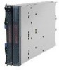
Power-control button: This button is behind the control panel door. Press this button to turn on or turn off the blade server. Note: The power-control button has effect only if local power control is enabled for the blade server. Local power control is enabled and disabled through the management-module Web interface. Blade server connectors The following illustration shows the system-board components, including connectors for user-installable options, for the blade server. Blade expansion Microprocessor 1 DIMM 4 DIMM 3 DIMM 2 DIMM 1 Microprocessor 2 Concurrent KVM MPE unit I/O-expansion card Battery Control panel SAS hard disk drive DIMM 8 DIMM 7 DIMM 6 DIMM 5 The following illustration shows the MPE components, including connectors for user-installable options. Blade expansion Microprocessor 1 DIMM 4 DIMM 3 DIMM 2 DIMM 1 Microprocessor 2 I/O-expansion card SAS hard disk drive DIMM 8 DIMM 7 DIMM 6 DIMM 5 16 BladeCenter LS21 Type 7971 and LS41 Type 7972: Installation and User's Guide
-
 1
1 -
2
-
3
-
4
-
5
-
6
-
7
-
8
-
9
-
10
-
11
-
12
-
13
-
14
-
15
-
16
-
17
-
18
-
19
-
20
-
21
-
22
-
 23
23 -
 24
24 -
 25
25 -
 26
26 -
 27
27 -
 28
28 -
 29
29 -
 30
30 -
 31
31 -
 32
32 -
 33
33 -
34
-
35
-
36
-
37
-
38
-
39
-
40
-
41
-
42
-
43
-
44
-
45
-
46
-
47
-
48
-
49
-
50
-
51
-
52
-
53
-
54
-
55
-
56
-
57
-
58
-
59
-
60
-
61
-
62
-
63
-
64
-
65
-
66
-
67
-
68
-
69
-
70
-
71
-
72
-
73
-
74
-
75
-
76
-
77
-
78
-
79
-
80
-
81
-
82
-
83
-
84
 |
 |
