IBM x3755 Installation Guide - Page 65
Light path diagnostics panel, LEDs on server components, Light Path, Diagnostics - specs
 |
View all IBM x3755 manuals
Add to My Manuals
Save this manual to your list of manuals |
Page 65 highlights
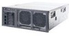
v If the system-error LED is lit, it indicates that there is a fault or condition in the server and that light path diagnostics might light an additional LED to help diagnose the problem. The following illustration shows the operator information panel. Locator LED Information LED Hard disk drive activity LED System-error LED Power-on LED Power-control button Release latch USB connectors 2. Light path diagnostics panel: To access the light path diagnostics panel, press the release latch on the front of the operator information drawer to the left; then, slide it forward. Note any LEDs that are lit, and then close the drawer. Light Path Diagnostics REMIND OVER SPEC PS1 PS2 CPU CNFG MEM NMI S ERR SP DASD RAID FAN TEMP BRD PCI 3. LEDs on server components: Remove the top cover to look inside the server for lit LEDs. To identify the component that is causing the error, note the lit LED on or next to the component. For example, a microprocessor/memory card error will light the LED on top of the microprocessor/memory card. The following illustration shows the LEDs on the I/O board. Chapter 6. Solving problems 53
-
 1
1 -
2
-
3
-
4
-
5
-
6
-
7
-
8
-
9
-
10
-
11
-
12
-
13
-
14
-
15
-
16
-
17
-
18
-
19
-
20
-
21
-
22
-
23
-
24
-
25
-
26
-
27
-
28
-
29
-
30
-
31
-
32
-
33
-
34
-
35
-
36
-
37
-
38
-
39
-
40
-
41
-
42
-
43
-
44
-
45
-
46
-
47
-
48
-
49
-
50
-
51
-
52
-
53
-
54
-
55
-
56
-
57
-
58
-
59
-
 60
60 -
 61
61 -
 62
62 -
 63
63 -
 64
64 -
 65
65 -
 66
66 -
 67
67 -
 68
68 -
 69
69 -
 70
70 -
71
-
72
-
73
-
74
-
75
-
76
-
77
-
78
-
79
-
80
-
81
-
82
-
83
-
84
-
85
-
86
-
87
-
88
 |
 |
