Intel D2550DC2 Product guide for Intel Desktop Board D2550DC2 - Page 7

s, Tables, Front Panel USB Header with Intel Z-U130 USB Solid-State Drive or

Page 7 highlights

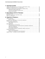
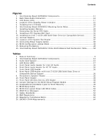
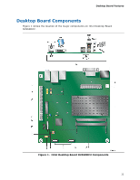
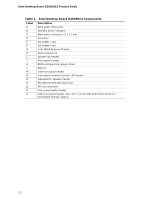
Contents Figures 1. Intel Desktop Board D2550DC2 Components 11 2. Back Panel Audio Connectors 16 3. LAN Status LEDs 17 4. Location of the Standby Power Indicator 21 5. Installing the I/O Shield 26 6. Intel Desktop Board D2550DC2 Mounting Screw Holes 27 7. Installing System Memory 28 8. Connecting the Serial ATA Cable 29 9. Installing a PCI Express Mini Card 31 10. Installing an Intel Z-U130 USB Solid-State Drive (or Compatible Device 32 11. Internal Headers 33 12. Location of the System Fan Header 37 13. Connecting Power Supply Cables 38 14. BIOS Configuration Jumper Block 39 15. Removing the Battery 45 16. Intel Desktop Board D2550DC2 China RoHS Material Self Declaration Table .......... 58 Tables 1. Feature Summary 9 2. Intel Desktop Board D2550DC2 Components 12 3. Audio Jack Support 15 4. LAN Status LEDs 17 5. Front Panel Audio Header for Intel HD Audio 34 6. Front Panel Audio Header for AC '97 Audio 34 7. Front Panel USB Header 35 8. Front Panel USB Header with Intel Z-U130 USB Solid-State Drive or Compatible Device Support 35 9. Piezoelectric Speaker Header 35 10. Front Panel Header 36 11. Front Panel Wireless Activity LED Header 36 12. Jumper Settings for the BIOS Setup Program Modes 40 13. Acceptable Drives/Media Types for BIOS Recovery 49 14. BIOS Beep Codes 51 15. BIOS Front-panel Power LED Blink Codes 52 16. POST Error Messages 52 17. Safety Standards 53 18. EMC Regulations 59 19. Regulatory Compliance Marks 62 20. ENERGY STAR Requirements 64 vii

  • 1
  • 2
  • 3
  • 4
  • 5
  • 6
  • 7
  • 8
  • 9
  • 10
  • 11
  • 12
  • 13
  • 14
  • 15
  • 16
  • 17
  • 18
  • 19
  • 20
  • 21
  • 22
  • 23
  • 24
  • 25
  • 26
  • 27
  • 28
  • 29
  • 30
  • 31
  • 32
  • 33
  • 34
  • 35
  • 36
  • 37
  • 38
  • 39
  • 40
  • 41
  • 42
  • 43
  • 44
  • 45
  • 46
  • 47
  • 48
  • 49
  • 50
  • 51
  • 52
  • 53
  • 54
  • 55
  • 56
  • 57
  • 58
  • 59
  • 60
  • 61
  • 62
  • 63
  • 64

Contents
vii
Figures
1. Intel Desktop Board D2550DC2 Components
.....................................................
11
2. Back Panel Audio Connectors
..........................................................................
16
3. LAN Status LEDs
............................................................................................
17
4.
Location of the Standby Power Indicator
...........................................................
21
5. Installing the I/O Shield
.................................................................................
26
6.
Intel Desktop Board D2550DC2 Mounting Screw Holes
.......................................
27
7. Installing System Memory
..............................................................................
28
8. Connecting the Serial ATA Cable
......................................................................
29
9.
Installing a PCI Express Mini Card
....................................................................
31
10. Installing an Intel Z-U130 USB Solid-State Drive (or Compatible Device)
..............
32
11. Internal Headers
...........................................................................................
33
12. Location of the System Fan Header
..................................................................
37
13. Connecting Power Supply Cables
.....................................................................
38
14. BIOS Configuration Jumper Block
....................................................................
39
15. Removing the Battery
....................................................................................
45
16. Intel Desktop Board D2550DC2 China RoHS Material Self Declaration Table
..........
58
Tables
1.
Feature Summary
............................................................................................
9
2.
Intel Desktop Board D2550DC2 Components
.....................................................
12
3.
Audio Jack Support
........................................................................................
15
4.
LAN Status LEDs
............................................................................................
17
5.
Front Panel Audio Header for Intel HD Audio
.....................................................
34
6.
Front Panel Audio Header for AC ‘97 Audio
........................................................
34
7.
Front Panel USB Header
.................................................................................
35
8.
Front Panel USB Header with Intel Z-U130 USB Solid-State Drive or
Compatible Device Support
.............................................................................
35
9.
Piezoelectric Speaker Header
..........................................................................
35
10.
Front Panel Header
........................................................................................
36
11.
Front Panel Wireless Activity LED Header
..........................................................
36
12.
Jumper Settings for the BIOS Setup Program Modes
..........................................
40
13.
Acceptable Drives/Media Types for BIOS Recovery
.............................................
49
14.
BIOS Beep Codes
..........................................................................................
51
15.
BIOS Front-panel Power LED Blink Codes
..........................................................
52
16.
POST Error Messages
.....................................................................................
52
17.
Safety Standards
...........................................................................................
53
18.
EMC Regulations
............................................................................................
59
19.
Regulatory Compliance Marks
.........................................................................
62
20.
ENERGY STAR Requirements
...........................................................................
64