Intel D845GLLY D845GLLY_ProductSupplement - Page 12
Connectors, CAUTION, INTEGRATOR, S NOTE
 |
View all Intel D845GLLY manuals
Add to My Manuals
Save this manual to your list of manuals |
Page 12 highlights
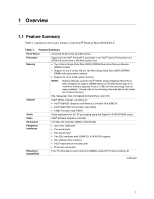
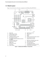
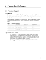
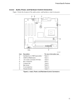
Product Supplement Document for the Intel Desktop Board D845GLLY 2.2 Connectors CAUTION Only the back panel USB, front panel USB, VGA, and PS/2 connectors have overcurrent protection. The Desktop Boards' internal connectors are not overcurrent protected and should connect only to devices inside the computer's chassis, such as fans and internal peripherals. Do not use these connectors to power devices external to the computer's chassis. A fault in the load presented by the external devices could cause damage to the computer, the interconnecting cable, and the external devices themselves. This section describes the Desktop Board's connectors. The connectors can be divided into the following groups: • Back panel I/O connectors (see page 13) PS/2 keyboard and mouse USB Parallel port Serial port VGA LAN (optional) Audio (line out, line in, and mic in) • Internal I/O connectors (see page 14) Audio (auxiliary line input and ATAPI CD-ROM) Fans Power Add-in boards (PCI) IDE Diskette drive Chassis intrusion • External I/O connectors (see page 19) Front panel USB Front panel (power/sleep/message-waiting LED, power switch, hard drive activity LED, reset switch, and auxiliary front panel power LED) Auxiliary front panel power/sleep/message-waiting LED @ INTEGRATOR'S NOTE When installing the Desktop Board in a microATX chassis, make sure that peripheral devices are installed at least 1.5 inches above the main power connector, the diskette drive connector, the IDE connector, and the DIMM sockets. 12
-
 1
1 -
2
-
3
-
4
-
5
-
6
-
 7
7 -
 8
8 -
 9
9 -
 10
10 -
 11
11 -
 12
12 -
 13
13 -
 14
14 -
 15
15 -
 16
16 -
 17
17 -
18
-
19
-
20
-
21
-
22
-
23
-
24
-
25
-
26
-
27
-
28
-
29
-
30
-
31
-
32
-
33
-
34
 |
 |
