Intel D845GLLY D845GLLY_ProductSupplement - Page 20
Integrator, S Note
 |
View all Intel D845GLLY manuals
Add to My Manuals
Save this manual to your list of manuals |
Page 20 highlights
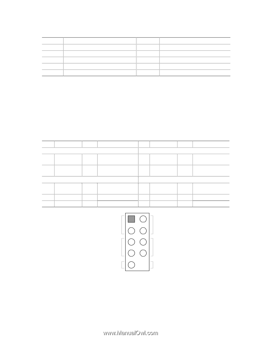
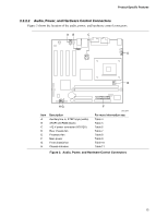
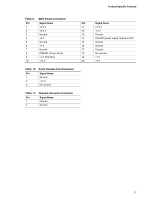
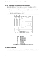
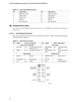
Product Supplement Document for the Intel Desktop Board D845GLLY Table 13. Front Panel USB Connector Pin Signal Name 1 USB_FNT_PWR 3 USB_FNTA# 5 USB_FNTA 7 Ground 9 Not connected Pin Signal Name 2 USB_FNT_PWR 4 USB_FNTB# 6 USB_FNTB 8 Ground 10 Not connected @ INTEGRATOR'S NOTE Use only a front panel USB connector that conforms to the USB 2.0 specification for high-speed USB devices. 2.2.3.1 Front Panel Connector This section describes the functions of the front panel connector. Table 14 lists the signal names of the front panel connector. Table 14. Front Panel Connector Pin Signal In/Out Description Pin Hard Drive Activity LED 1 HD_PWR Out Hard disk LED pull-up 2 (330 Ω) to +5 V 3 HAD# Out Hard disk active LED 4 Reset Switch 5 Ground Ground 6 7 FP_RESET# In Reset switch 8 9 +5 V Out Power 10 Signal In/Out Description Power LED HDR_BLNK_ Out GRN Front panel green LED HDR_BLNK_ Out YEL Front panel yellow LED On/Off Switch SWITCH_ON In # Power switch Ground Ground N/C Not connected 12 Hard Drive Activity LED 34 56 Reset Switch 78 +5 V DC 9 Power LED Power Switch N/C OM14561 20
-
 1
1 -
2
-
3
-
4
-
5
-
6
-
7
-
8
-
9
-
10
-
11
-
12
-
13
-
14
-
 15
15 -
 16
16 -
 17
17 -
 18
18 -
 19
19 -
 20
20 -
 21
21 -
 22
22 -
 23
23 -
 24
24 -
 25
25 -
26
-
27
-
28
-
29
-
30
-
31
-
32
-
33
-
34
 |
 |