Intel D845GLLY D845GLLY_ProductSupplement - Page 22
Auxiliary Front Panel Power/Sleep/Message-Waiting LED Connector
 |
View all Intel D845GLLY manuals
Add to My Manuals
Save this manual to your list of manuals |
Page 22 highlights
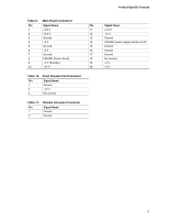
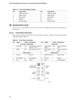
Product Supplement Document for the Intel Desktop Board D845GLLY 2.2.3.1.4 Power Switch Connector Pins 6 and 8 can be connected to a front panel momentary-contact power switch. The switch must pull the SW_ON# pin to ground for at least 50 ms to signal the power supply to switch on or off. (The time requirement is due to internal debounce circuitry on the Desktop Board D845GLLY.) At least two seconds must pass before the power supply will recognize another on/off signal. 2.2.3.2 Auxiliary Front Panel Power/Sleep/Message-Waiting LED Connector Pins 1 and 3 of this connector duplicate the signals on pins 2 and 4 of the front panel connector. Table 17 lists the signal names of the Auxiliary Front Panel Power/Sleep/Message-Waiting LED Connector. Table 17. Auxiliary Front Panel Power/Sleep/Message-Waiting LED Connector Pin Signal Name In/Out Description 1 HDR_BLNK_GRN Out Front panel green LED 2 Not connected 3 HDR_BLNK_YEL Out Front panel yellow LED 22
-
 1
1 -
2
-
3
-
4
-
5
-
6
-
7
-
8
-
9
-
10
-
11
-
12
-
13
-
14
-
15
-
16
-
 17
17 -
 18
18 -
 19
19 -
 20
20 -
 21
21 -
 22
22 -
 23
23 -
 24
24 -
 25
25 -
 26
26 -
 27
27 -
28
-
29
-
30
-
31
-
32
-
33
-
34
 |
 |
