Intel D845GLLY D845GLLY_ProductSupplement - Page 21
Integrator, S Note
 |
View all Intel D845GLLY manuals
Add to My Manuals
Save this manual to your list of manuals |
Page 21 highlights
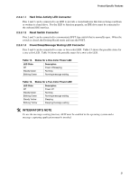
Product-Specific Features 2.2.3.1.1 Hard Drive Activity LED Connector Pins 1 and 3 can be connected to an LED to provide a visual indicator that data is being read from or written to a hard drive. For the LED to function properly, an IDE drive must be connected to the onboard IDE interface. 2.2.3.1.2 Reset Switch Connector Pins 5 and 7 can be connected to a momentary SPST type switch that is normally open. When the switch is closed, the Desktop Board resets and runs the POST. 2.2.3.1.3 Power/Sleep/Message Waiting LED Connector Pins 2 and 4 can be connected to a one- or two-color LED. Table 15 shows the possible states for a one-color LED. Table 16 shows the possible states for a two-color LED. Table 15. States for a One-Color Power LED LED State Description Off Power off/sleeping Steady Green Running Blinking Green Running/message waiting Table 16. States for a Two-Color Power LED LED State Off Steady Green Blinking Green Steady Yellow Blinking Yellow Description Power off Running Running/message waiting Sleeping Sleeping/message waiting @ INTEGRATOR'S NOTE To use the message waiting function, ACPI must be enabled in the operating system and a message-capturing application must be invoked. 21
-
 1
1 -
2
-
3
-
4
-
5
-
6
-
7
-
8
-
9
-
10
-
11
-
12
-
13
-
14
-
15
-
 16
16 -
 17
17 -
 18
18 -
 19
19 -
 20
20 -
 21
21 -
 22
22 -
 23
23 -
 24
24 -
 25
25 -
 26
26 -
27
-
28
-
29
-
30
-
31
-
32
-
33
-
34
 |
 |
