Intel D845GLLY D845GLLY_ProductSupplement - Page 18
Add-in Board and Peripheral Interface Connectors, INTEGRATOR, S NOTE,
 |
View all Intel D845GLLY manuals
Add to My Manuals
Save this manual to your list of manuals |
Page 18 highlights
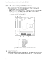
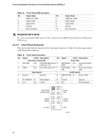
Product Supplement Document for the Intel Desktop Board D845GLLY 2.2.2.3 Add-in Board and Peripheral Interface Connectors Figure 4 shows the location of the add-in board connector and peripheral connectors for the Desktop Board D845GLLY. Note the following considerations for the PCI bus connectors: • All of the PCI bus connectors are bus master capable. • SMBus signals are routed to PCI bus connector 2, enabling PCI bus add-in boards with SMBus support to access sensor data on the Desktop Board. The SMBus signals are as follows: The SMBus clock line is connected to pin A40. The SMBus data line is connected to pin A41. A BCD 2 1 2 1 G F 40 39 2 40 34 39 33 1 E Item A B C D E F G Description PCI bus connector 4 PCI bus connector 3 PCI bus connector 2 PCI bus connector 1 Diskette drive Primary IDE Secondary IDE OM13645 Figure 4. Add-in Board and Peripheral Interface Connectors @ INTEGRATOR'S NOTE Not all PCI video cards can be used in PCI bus connectors 1 and 2 (the PCI bus connectors closest to the processor). To avoid clearance problems, install PCI video cards in PCI bus connector 3. 18
-
 1
1 -
2
-
3
-
4
-
5
-
6
-
7
-
8
-
9
-
10
-
11
-
12
-
 13
13 -
 14
14 -
 15
15 -
 16
16 -
 17
17 -
 18
18 -
 19
19 -
 20
20 -
 21
21 -
 22
22 -
 23
23 -
24
-
25
-
26
-
27
-
28
-
29
-
30
-
31
-
32
-
33
-
34
 |
 |
