Intel D845GLLY D845GLLY_ProductSupplement - Page 17
Table 9., Main Power Connector, Front Chassis Fan Connector, Chassis Intrusion Connector, 3.3 V
 |
View all Intel D845GLLY manuals
Add to My Manuals
Save this manual to your list of manuals |
Page 17 highlights
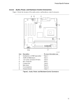
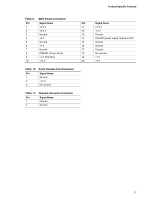
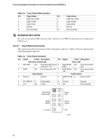
Product-Specific Features Table 9. Main Power Connector Pin Signal Name Pin 1 +3.3 V 11 2 +3.3 V 12 3 Ground 13 4 +5 V 14 5 Ground 15 6 +5 V 16 7 Ground 17 8 PWRGD (Power Good) 18 9 +5 V (Standby) 19 10 +12 V 20 Table 10. Front Chassis Fan Connector Pin Signal Name 1 Ground 2 +12 V 3 No connect Table 11. Chassis Intrusion Connector Pin Signal Name 1 Intruder 2 Ground Signal Name +3.3 V -12 V Ground PS-ON# (power supply remote on/off) Ground Ground Ground No connect +5 V +5 V 17
-
 1
1 -
2
-
3
-
4
-
5
-
6
-
7
-
8
-
9
-
10
-
11
-
 12
12 -
 13
13 -
 14
14 -
 15
15 -
 16
16 -
 17
17 -
 18
18 -
 19
19 -
 20
20 -
 21
21 -
 22
22 -
23
-
24
-
25
-
26
-
27
-
28
-
29
-
30
-
31
-
32
-
33
-
34
 |
 |

Product-Specific Features
17
Table 9.
Main Power Connector
Pin
Signal Name
Pin
Signal Name
1
+3.3 V
11
+3.3 V
2
+3.3 V
12
-12 V
3
Ground
13
Ground
4
+5 V
14
PS-ON# (power supply remote on/off)
5
Ground
15
Ground
6
+5 V
16
Ground
7
Ground
17
Ground
8
PWRGD (Power Good)
18
No connect
9
+5 V (Standby)
19
+5 V
10
+12 V
20
+5 V
Table 10.
Front Chassis Fan Connector
Pin
Signal Name
1
Ground
2
+12 V
3
No connect
Table 11.
Chassis Intrusion Connector
Pin
Signal Name
1
Intruder
2
Ground