Intel D845GLLY D845GLLY_ProductSupplement - Page 19
External I/O Connectors, Table 12., Serial Port B Connector
 |
View all Intel D845GLLY manuals
Add to My Manuals
Save this manual to your list of manuals |
Page 19 highlights
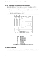
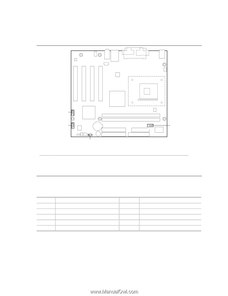
2.2.3 External I/O Connectors Figure 5 shows the locations of the external I/O connectors. Product-Specific Features Item A B C D 1 D7 2 10 1 2 C 8 9 13 91 A 82 B OM13646 Description Serial port B Auxiliary front panel power/sleep/message-waiting LED Front panel Front panel USB For more information see: Table 12 Table 17 Table 14 Table 13 Figure 5. External I/O Connectors Table 12. Serial Port B Connector Pin Signal Name 1 DCD 3 TXD 5 Ground 7 RTS 9 RI Pin Signal Name 2 RXD 4 DTR 6 DSR 8 CTS 10 Not connected 19
-
 1
1 -
2
-
3
-
4
-
5
-
6
-
7
-
8
-
9
-
10
-
11
-
12
-
13
-
 14
14 -
 15
15 -
 16
16 -
 17
17 -
 18
18 -
 19
19 -
 20
20 -
 21
21 -
 22
22 -
 23
23 -
 24
24 -
25
-
26
-
27
-
28
-
29
-
30
-
31
-
32
-
33
-
34
 |
 |
Product-Specific Features
19
2.2.3
External I/O Connectors
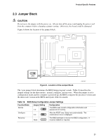
Figure 5 shows the locations of the external I/O connectors.
B
OM13646
7
10
2
1
9
8
2
1
13
C
D
9
1
8
2
A
Item
Description
For more information see:
A
Serial port B
Table 12
B
Auxiliary front panel power/sleep/message-waiting LED
Table 17
C
Front panel
Table 14
D
Front panel USB
Table 13
Figure 5.
External I/O Connectors
Table 12.
Serial Port B Connector
Pin
Signal Name
Pin
Signal Name
1
DCD
2
RXD
3
TXD
4
DTR
5
Ground
6
DSR
7
RTS
8
CTS
9
RI
10
Not connected