Intel D915GUX Product Specification - Page 29
Audio Subsystem - audio drivers
 |
View all Intel D915GUX manuals
Add to My Manuals
Save this manual to your list of manuals |
Page 29 highlights
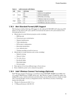
Product Description 1.9 Audio Subsystem The boards support the Intel High Definition Audio subsystem based on the Realtek ALC860 codec. The audio subsystem supports the following features: • Advanced jack sense (front and rear panel) that enables the audio codec to recognize the device that is connected to an audio port. All jacks are capable of retasking according to user's definition, or can be automatically switched depending on the recognized device type. • Stereo input and output for all jacks. • A signal-to-noise (S/N) ratio of 90 dB. # INTEGRATOR'S NOTE For the front panel jack sensing and automatic retasking feature to function, a front panel daughter card that is designed for Intel High Definition Audio must be used. Otherwise, an AC '97 style audio front panel connector will be assumed and the Line Out and Mic In functions will be permanent. 1.9.1 Audio Subsystem Software Audio software and drivers are available from Intel's World Wide Web site. For information about Refer to Obtaining audio software and drivers Section 1.3, page 17 1.9.2 Audio Connectors The boards contain audio connector on both the back panel and the component side of the board. The component-side audio connectors include the following: • Front panel audio (a 2 x 5-pin connector that provides mic in and line out signals for front panel audio connectors) • ATAPI CD-ROM (an optional 1 x 4-pin ATAPI-style connector for connecting an internal ATAPI CD-ROM drive to the audio mixer) • S/PDIF (an optional 1 x 3 connector that provides S/PDIF output signals) The functions of the back panel audio connectors are dependent on which subsystem is present. For information about The location of the front panel audio connector, the optional ATAPI CD-ROM connector, and the optional S/PDIF connector The signal names of the front panel audio connector The signal names of the optional ATAPI CD-ROM connector The signal names of the optional S/PDIF connector Refer to Figure 17, page 58 Table 20, page 60 Table 19, page 60 Table 18, page 60 29
-
 1
1 -
2
-
3
-
4
-
5
-
6
-
7
-
8
-
9
-
10
-
11
-
12
-
13
-
14
-
15
-
16
-
17
-
18
-
19
-
20
-
21
-
22
-
23
-
 24
24 -
 25
25 -
 26
26 -
 27
27 -
 28
28 -
 29
29 -
 30
30 -
 31
31 -
 32
32 -
 33
33 -
 34
34 -
35
-
36
-
37
-
38
-
39
-
40
-
41
-
42
-
43
-
44
-
45
-
46
-
47
-
48
-
49
-
50
-
51
-
52
-
53
-
54
-
55
-
56
-
57
-
58
-
59
-
60
-
61
-
62
-
63
-
64
-
65
-
66
-
67
-
68
-
69
-
70
-
71
-
72
-
73
-
74
-
75
-
76
-
77
-
78
-
79
-
80
-
81
-
82
-
83
-
84
-
85
-
86
-
87
-
88
-
89
-
90
-
91
-
92
-
93
-
94
 |
 |