Intel D915GUX Product Specification - Page 70
Electrical Considerations
 |
View all Intel D915GUX manuals
Add to My Manuals
Save this manual to your list of manuals |
Page 70 highlights
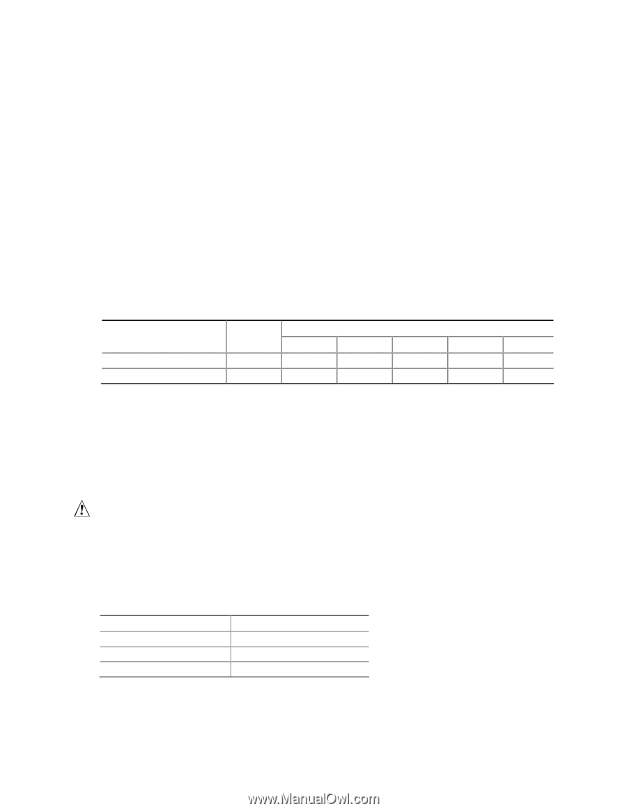
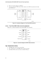
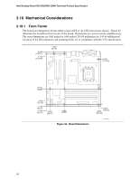
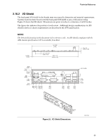
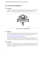
Intel Desktop Board D915GUX/D915GHA Technical Product Specification 2.11 Electrical Considerations 2.11.1 DC Loading Table 35 lists the DC loading characteristics of the board. This data is based on a DC analysis of all active components within the board that impact its power delivery subsystems. The analysis does not include PCI add-in cards. Minimum values assume a light load placed on the board that is similar to an environment with no applications running and no USB current draw. Maximum values assume a load placed on the board that is similar to a heavy gaming environment with a 500 mA current draw per USB port. These calculations are not based on specific processor values or memory configurations but are based on the minimum and maximum current draw possible from the board's power delivery subsystems to the processor, memory, and USB ports. Use the datasheets for add-in cards, such as PCI, to determine the overall system power requirements. The selection of a power supply at the system level is dependent on the system's usage model and not necessarily tied to a particular processor speed. Table 35. DC Loading Characteristics Mode Minimum loading Maximum loading DC Power 200.00 W 300.00 W +3.3 V 3.30 A 6.00 A +5 V 10.00 A 14.00 A DC Current at: +12 V -12 V 9.00 A 0.03 A 16.00 A 0.10 A +5 VSB 0.80 A 1.40 A 2.11.2 Add-in Board Considerations The boards are designed to provide 2 A (average) of +5 V current for each add-in board. The total +5 V current draw for a fully loaded board (all three expansion slots and the PCI Express x16 slot filled) must not exceed 8 A. 2.11.3 Fan Connector Current Capability CAUTION The processor fan must be connected to the processor fan connector, not to a chassis fan connector. Connecting the processor fan to a chassis fan connector may result in onboard component damage that will halt fan operation. Table 36 lists the current capability of the fan connectors. Table 36. Fan Connector Current Capability Fan Connector Processor fan Front chassis fan Rear chassis fan Maximum Available Current 1000 mA 600 mA 600 mA 70
-
 1
1 -
2
-
3
-
4
-
5
-
6
-
7
-
8
-
9
-
10
-
11
-
12
-
13
-
14
-
15
-
16
-
17
-
18
-
19
-
20
-
21
-
22
-
23
-
24
-
25
-
26
-
27
-
28
-
29
-
30
-
31
-
32
-
33
-
34
-
35
-
36
-
37
-
38
-
39
-
40
-
41
-
42
-
43
-
44
-
45
-
46
-
47
-
48
-
49
-
50
-
51
-
52
-
53
-
54
-
55
-
56
-
57
-
58
-
59
-
60
-
61
-
62
-
63
-
64
-
 65
65 -
 66
66 -
 67
67 -
 68
68 -
 69
69 -
 70
70 -
 71
71 -
 72
72 -
 73
73 -
 74
74 -
 75
75 -
76
-
77
-
78
-
79
-
80
-
81
-
82
-
83
-
84
-
85
-
86
-
87
-
88
-
89
-
90
-
91
-
92
-
93
-
94
 |
 |