Intel D915GUX Product Specification - Page 56
Connectors
 |
View all Intel D915GUX manuals
Add to My Manuals
Save this manual to your list of manuals |
Page 56 highlights
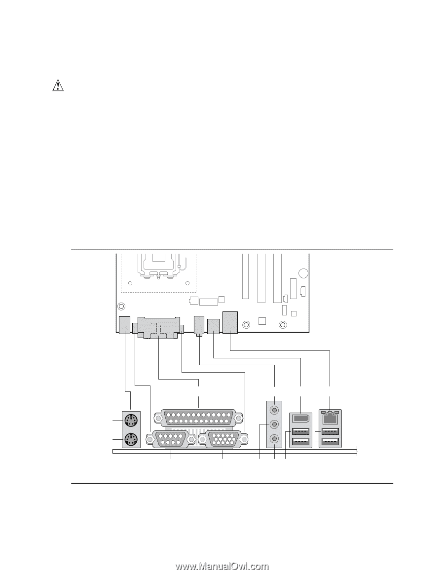
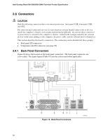
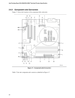
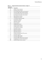
Intel Desktop Board D915GUX/D915GHA Technical Product Specification 2.8 Connectors CAUTION Only the following connectors have overcurrent protection: back panel USB, front panel USB, and PS/2. The other internal connectors are not overcurrent protected and should connect only to devices inside the computer's chassis, such as fans and internal peripherals. Do not use these connectors to power devices external to the computer's chassis. A fault in the load presented by the external devices could cause damage to the computer, the power cable, and the external devices themselves. This section describes the board's connectors. The connectors can be divided into these groups: • Back panel I/O connectors • Component-side I/O connectors (see page 58) 2.8.1 Back Panel Connectors Figure 16 shows the location of the back panel connectors. The back panel connectors are color-coded. The figure legend (Table 16) lists the colors used (when applicable). C F I K A B D E G HJ L Figure 16. Back Panel Connectors OM16660 56
-
 1
1 -
2
-
3
-
4
-
5
-
6
-
7
-
8
-
9
-
10
-
11
-
12
-
13
-
14
-
15
-
16
-
17
-
18
-
19
-
20
-
21
-
22
-
23
-
24
-
25
-
26
-
27
-
28
-
29
-
30
-
31
-
32
-
33
-
34
-
35
-
36
-
37
-
38
-
39
-
40
-
41
-
42
-
43
-
44
-
45
-
46
-
47
-
48
-
49
-
50
-
 51
51 -
 52
52 -
 53
53 -
 54
54 -
 55
55 -
 56
56 -
 57
57 -
 58
58 -
 59
59 -
 60
60 -
 61
61 -
62
-
63
-
64
-
65
-
66
-
67
-
68
-
69
-
70
-
71
-
72
-
73
-
74
-
75
-
76
-
77
-
78
-
79
-
80
-
81
-
82
-
83
-
84
-
85
-
86
-
87
-
88
-
89
-
90
-
91
-
92
-
93
-
94
 |
 |