Intel DG41MJ Product Guide - Page 16
LAN Subsystem, LAN Connector LEDs, Table 4. LAN Connector LEDs
 |
UPC - 735858206907
View all Intel DG41MJ manuals
Add to My Manuals
Save this manual to your list of manuals |
Page 16 highlights
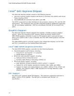
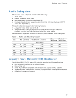
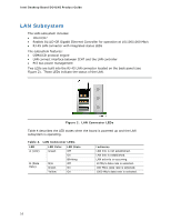
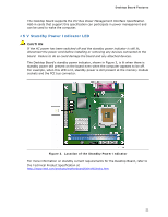
Intel Desktop Board DG41MJ Product Guide LAN Subsystem The LAN subsystem includes: • Intel ICH7 • Realtek 8111D-GR Gigabit Ethernet Controller for operation at 10/100/1000 Mb/s • RJ-45 LAN connector with integrated status LEDs The subsystem features: • CSMA/CD protocol engine • LAN connect interface between ICH7 and the LAN controller • PCI bus power management Two LEDs are built into the RJ-45 LAN connector located on the back panel (see Figure 2). These LEDs indicate the status of the LAN. Figure 2. LAN Connector LEDs Table 4 describes the LED states when the board is powered up and the LAN subsystem is operating. Table 4. LAN Connector LEDs LED A (Link) B (Data Rate) LED Color Green N/A Green Yellow LED State Off On Blinking Off On On Indicates LAN link is not established. LAN link is established. LAN activity is occurring. 10 Mb/s data rate is selected. 100 Mb/s data rate is selected. 1000 Mb/s data rate is selected. 16
-
 1
1 -
2
-
3
-
4
-
5
-
6
-
7
-
8
-
9
-
10
-
 11
11 -
 12
12 -
 13
13 -
 14
14 -
 15
15 -
 16
16 -
 17
17 -
 18
18 -
 19
19 -
 20
20 -
 21
21 -
22
-
23
-
24
-
25
-
26
-
27
-
28
-
29
-
30
-
31
-
32
-
33
-
34
-
35
-
36
-
37
-
38
-
39
-
40
-
41
-
42
-
43
-
44
-
45
-
46
-
47
-
48
-
49
-
50
-
51
-
52
-
53
-
54
-
55
-
56
-
57
-
58
-
59
-
60
-
61
-
62
-
63
-
64
-
65
-
66
-
67
-
68
 |
 |
