Intel DP35DP Product Guide - Page 48
Connecting to the Consumer IR (CIR) Headers - cant get to bios
 |
UPC - 735858192453
View all Intel DP35DP manuals
Add to My Manuals
Save this manual to your list of manuals |
Page 48 highlights
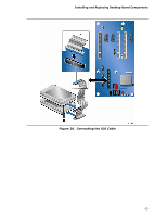
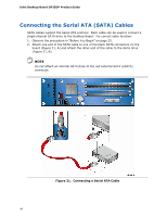
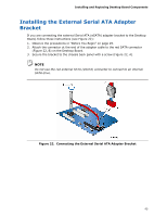
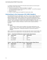
Intel Desktop Board DP35DP Product Guide To install the cable that connects the front panel audio solution to the front panel audio header, follow these steps: 1. Observe the precautions in "Before You Begin" on page 25. 2. Turn off all peripheral devices connected to the computer. Turn off the computer and disconnect the AC power cord. 3. Remove the cover. 4. Install a correctly keyed and shielded front panel audio cable. Connecting to the Consumer IR (CIR) Headers The Desktop Board has two CIR headers: the input or receiver header (Figure 23, F) and the output or emitter header (Figure 23, D). The receiver header consists of a filtered translated infrared input compliant with Microsoft CIR specifications and a "learning" infrared input. The learning input is a high-pass input which the computer can use to "learn" to speak the infrared communication language of other user remotes. The emitter header consists of two output ports which the computer can use to emulate "learned" infrared commands in order to control external electronic hardware. NOTE The Consumer IR option must be enabled in the system BIOS before it can function. Press at boot to enter the system BIOS, and go to Advanced > Peripheral Configuration > Enhanced Consumer IR, and set this option to Enabled. Table 7 shows the pin assignments for the front panel CIR receiver (input) header and Table 8 shows the pin assignments for the back panel CIR emitter (output) header. Table 7. Front Panel CIR Receiver (Input) Header Signal Names Pin Signal Name 1 Ground 3 No Connection 5 +5 V Standby 7 Key (no pin) Pin Signal Name 2 LED 4 Learn-In 6 Vcc 8 CIR Input Table 8. Back Panel CIR Header Emitter (Output) Header Signal Names Pin Signal Name 1 Emitter Out 1 3 Ground 5 Jack Detect 1 Pin Signal Name 2 Emitter Out 2 4 Key (no pin) 6 Jack Detect 2 48
-
 1
1 -
2
-
3
-
4
-
5
-
6
-
7
-
8
-
9
-
10
-
11
-
12
-
13
-
14
-
15
-
16
-
17
-
18
-
19
-
20
-
21
-
22
-
23
-
24
-
25
-
26
-
27
-
28
-
29
-
30
-
31
-
32
-
33
-
34
-
35
-
36
-
37
-
38
-
39
-
40
-
41
-
42
-
 43
43 -
 44
44 -
 45
45 -
 46
46 -
 47
47 -
 48
48 -
 49
49 -
 50
50 -
 51
51 -
 52
52 -
 53
53 -
54
-
55
-
56
-
57
-
58
-
59
-
60
-
61
-
62
-
63
-
64
-
65
-
66
-
67
-
68
-
69
-
70
-
71
-
72
-
73
-
74
-
75
-
76
-
77
-
78
-
79
-
80
-
81
-
82
-
83
-
84
 |
 |