Intel DP35DP Product Guide - Page 7

Connecting the Processor Fan Heat Sink Cable to the Processor Fan Header - board

Page 7 highlights

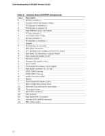
Contents 5 Configuring for Intel® Rapid Recover Technology Enabling Intel Rapid Recover Technology 67 Creating a Recovery Volume 68 Creating a Recovery Volume Using the RAID Option ROM 68 Creating a Recovery Volume Using the Intel Matrix Storage Console 68 Disk Synchronization Mode 69 Mounting the Recovery Disk 69 A Error Messages and Indicators BIOS Beep Codes 71 BIOS Error Messages 71 B Regulatory Compliance Safety Regulations 73 Place Battery Marking 73 European Union Declaration of Conformity Statement 74 Product Ecology Statements 76 Recycling Considerations 76 Lead-Free Desktop Board 78 EMC Regulations 80 Ensure Electromagnetic Compatibility (EMC) Compliance 81 Product Certifications 82 Board-Level Certification Markings 82 Chassis and Component Certifications 83 Figures 1. Desktop Board DP35DP Components 11 2. LAN Connector LEDs 16 3. Location of the Standby Power Indicator 23 4. Installing the I/O Shield 27 5. Desktop Board DP35DP Mounting Screw Hole Locations 28 6. Lift the Socket Lever 29 7. Lift the Load Plate 30 8. Remove the Protective Socket Cover 30 9. Remove the Processor from the Protective Processor Cover 31 10. Install the Processor 31 11. Close the Load Plate 32 12. Connecting the Processor Fan Heat Sink Cable to the Processor Fan Header ..........33 13. Dual Channel Memory Configuration with Two DIMMs 35 14. Dual Channel Memory Configuration with Four DIMMs 35 15. Dual Channel Memory Configuration with Three DIMMs 36 16. Use DDR2 DIMMs 37 17. Installing a DIMM 38 18. Installing a PCI Express x16 Card 40 19. Removing a PCI Express x16 Card 41 20. Connecting the IDE Cable 43 21. Connecting a Serial ATA Cable 44 22. Connecting the External Serial ATA Adapter Bracket 45 23. Internal Headers 46 24. Back Panel Audio Connectors 51 25. Location of the Chassis Fan Headers 52 vii

  • 1
  • 2
  • 3
  • 4
  • 5
  • 6
  • 7
  • 8
  • 9
  • 10
  • 11
  • 12
  • 13
  • 14
  • 15
  • 16
  • 17
  • 18
  • 19
  • 20
  • 21
  • 22
  • 23
  • 24
  • 25
  • 26
  • 27
  • 28
  • 29
  • 30
  • 31
  • 32
  • 33
  • 34
  • 35
  • 36
  • 37
  • 38
  • 39
  • 40
  • 41
  • 42
  • 43
  • 44
  • 45
  • 46
  • 47
  • 48
  • 49
  • 50
  • 51
  • 52
  • 53
  • 54
  • 55
  • 56
  • 57
  • 58
  • 59
  • 60
  • 61
  • 62
  • 63
  • 64
  • 65
  • 66
  • 67
  • 68
  • 69
  • 70
  • 71
  • 72
  • 73
  • 74
  • 75
  • 76
  • 77
  • 78
  • 79
  • 80
  • 81
  • 82
  • 83
  • 84

Contents
vii
5
Configuring for Intel
®
Rapid Recover Technology
Enabling Intel Rapid Recover Technology
...............................................................
67
Creating a Recovery Volume
................................................................................
68
Creating a Recovery Volume Using the RAID Option ROM
.................................
68
Creating a Recovery Volume Using the Intel Matrix Storage Console
..................
68
Disk Synchronization Mode
..................................................................................
69
Mounting the Recovery Disk
................................................................................
69
A
Error Messages and Indicators
BIOS Beep Codes
...............................................................................................
71
BIOS Error Messages
..........................................................................................
71
B
Regulatory Compliance
Safety Regulations
.............................................................................................
73
Place Battery Marking
.................................................................................
73
European Union Declaration of Conformity Statement
..............................................
74
Product Ecology Statements
................................................................................
76
Recycling Considerations
.............................................................................
76
Lead-Free Desktop Board
.............................................................................
78
EMC Regulations
................................................................................................
80
Ensure Electromagnetic Compatibility (EMC) Compliance
..................................
81
Product Certifications
..........................................................................................
82
Board-Level Certification Markings
................................................................
82
Chassis and Component Certifications
............................................................
83
Figures
1. Desktop Board DP35DP Components
...............................................................
11
2. LAN Connector LEDs
.....................................................................................
16
3.
Location of the Standby Power Indicator
..........................................................
23
4. Installing the I/O Shield
................................................................................
27
5.
Desktop Board DP35DP Mounting Screw Hole Locations
.....................................
28
6. Lift the Socket Lever
.....................................................................................
29
7. Lift the Load Plate
.........................................................................................
30
8. Remove the Protective Socket Cover
...............................................................
30
9.
Remove the Processor from the Protective Processor Cover
................................
31
10. Install the Processor
.....................................................................................
31
11. Close the Load Plate
.....................................................................................
32
12. Connecting the Processor Fan Heat Sink Cable to the Processor Fan Header
..........
33
13. Dual Channel Memory Configuration with Two DIMMs
........................................
35
14. Dual Channel Memory Configuration with Four DIMMs
........................................
35
15. Dual Channel Memory Configuration with Three DIMMs
......................................
36
16. Use DDR2 DIMMs
.........................................................................................
37
17. Installing a DIMM
.........................................................................................
38
18. Installing a PCI Express x16 Card
...................................................................
40
19. Removing a PCI Express x16 Card
..................................................................
41
20. Connecting the IDE Cable
..............................................................................
43
21. Connecting a Serial ATA Cable
........................................................................
44
22. Connecting the External Serial ATA Adapter Bracket
..........................................
45
23. Internal Headers
..........................................................................................
46
24. Back Panel Audio Connectors
.........................................................................
51
25. Location of the Chassis Fan Headers
................................................................
52