Intel DQ965CO DQ965CO Technical Product Specification - Page 20
Memory Configurations
 |
View all Intel DQ965CO manuals
Add to My Manuals
Save this manual to your list of manuals |
Page 20 highlights
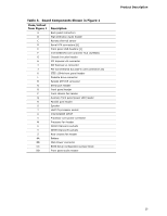
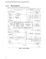
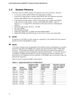
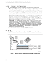
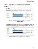
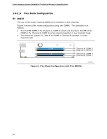
Intel Desktop Board DQ965CO Technical Product Specification 1.4.1 Memory Configurations The Intel 82Q965 GMCH supports the following types of memory organization: • Dual channel (Interleaved) mode. This mode offers the highest throughput for real world applications. Dual channel mode is enabled when the installed memory capacities of both DIMM channels are equal. Technology and device width can vary from one channel to the other but the installed memory capacity for each channel must be equal. If different speed DIMMs are used between channels, the slowest memory timing will be used. • Single channel (Asymmetric) mode. This mode is equivalent to single channel bandwidth operation for real world applications. This mode is used when only a single DIMM is installed or the memory capacities are unequal. Technology and device width can vary from one channel to the other. If different speed DIMMs are used between channels, the slowest memory timing will be used. • Flex mode. This mode provides the most flexible performance characteristics. The bottommost DRAM memory (the memory that is lowest within the system memory map) is mapped to dual channel operation; the topmost DRAM memory (the memory that is nearest to the 8 GB address space limit), if any, is mapped to single channel operation. Flex mode results in multiple zones of dual and single channel operation across the whole of DRAM memory. To use flex mode, it is necessary to populate both channels. Figure 3 illustrates the memory channel and DIMM configuration. NOTE The DIMM0 sockets of both channels are blue. The DIMM1 sockets of both channels are black. Channel A, DIMM 0 Channel A, DIMM 1 Channel B, DIMM 0 Channel B, DIMM 1 OM18322 Figure 3. Memory Channel Configuration and DIMM Configuration 20
-
 1
1 -
2
-
3
-
4
-
5
-
6
-
7
-
8
-
9
-
10
-
11
-
12
-
13
-
14
-
 15
15 -
 16
16 -
 17
17 -
 18
18 -
 19
19 -
 20
20 -
 21
21 -
 22
22 -
 23
23 -
 24
24 -
 25
25 -
26
-
27
-
28
-
29
-
30
-
31
-
32
-
33
-
34
-
35
-
36
-
37
-
38
-
39
-
40
-
41
-
42
-
43
-
44
-
45
-
46
-
47
-
48
-
49
-
50
-
51
-
52
-
53
-
54
-
55
-
56
-
57
-
58
-
59
-
60
-
61
-
62
-
63
-
64
-
65
-
66
-
67
-
68
-
69
-
70
-
71
-
72
-
73
-
74
-
75
-
76
-
77
-
78
-
79
-
80
-
81
-
82
-
83
-
84
-
85
-
86
-
87
-
88
-
89
-
90
-
91
-
92
-
93
-
94
-
95
-
96
-
97
-
98
-
99
-
100
-
101
-
102
 |
 |
