Intel SC5300BD2 Product Specification - Page 11
List of Tables - processors
 |
UPC - 735858171755
View all Intel SC5300BD2 manuals
Add to My Manuals
Save this manual to your list of manuals |
Page 11 highlights
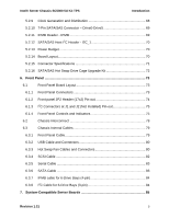
Introduction Intel® Server Chassis SC5300 5U Kit TPS List of Tables Table 1. Intel® Server Chassis SC5300BASE, SC5300BRP, and SC5300LX Features12 Table 2. Product Matrix 15 Table 3. Chassis Dimensions and Weights 17 Table 4. System Color Code 17 Table 5. 600-W and 730-W Power Supply Cable Lengths 24 Table 6. Baseboard Power Connector P1 Pin-out 26 Table 7. Processor Power Connector P2 26 Table 8. Power Signal Connector P13 27 Table 9. Peripheral Power Connectors 27 Table 10. Floppy Power Connector P6 28 Table 11. PCI Express Connector 28 Table 12. AC Input Ratings 29 Table 13. Maximum System Load Ratings 30 Table 14. Light System Load Ratings 30 Table 15. AC Input Rating 34 Table 16. Edge Finger Pin-out 35 Table 17. 730-W Load Ratings 36 Table 18. Voltage Regulation Limits 37 Table 19. Thermal Requirements 41 Table 20. Cable Lengths 41 Table 21. P1 Baseboard Power Connector 42 Table 22. P2 Processor Power Connector 43 Table 23. P3-P5, P7-P12 Peripheral Power Connectors 43 Table 24. P6 Floppy Power Connector 43 Table 25. Power Signal Connector 44 Table 26. +12V Outputs Load Ratings 44 Table 27. DC/DC Converters Load Ratings 45 Table 28. Voltage Regulation Limits 45 Table 29. Power Connector Pin-out 55 Table 30. SCA2 SCSI Connector Pin-out 55 10 Revision 1.31
-
 1
1 -
2
-
3
-
4
-
5
-
 6
6 -
 7
7 -
 8
8 -
 9
9 -
 10
10 -
 11
11 -
 12
12 -
 13
13 -
 14
14 -
 15
15 -
 16
16 -
17
-
18
-
19
-
20
-
21
-
22
-
23
-
24
-
25
-
26
-
27
-
28
-
29
-
30
-
31
-
32
-
33
-
34
-
35
-
36
-
37
-
38
-
39
-
40
-
41
-
42
-
43
-
44
-
45
-
46
-
47
-
48
-
49
-
50
-
51
-
52
-
53
-
54
-
55
-
56
-
57
-
58
-
59
-
60
-
61
-
62
-
63
-
64
-
65
-
66
-
67
-
68
-
69
-
70
-
71
-
72
-
73
-
74
-
75
-
76
-
77
-
78
-
79
-
80
-
81
-
82
-
83
-
84
-
85
-
86
-
87
-
88
-
89
-
90
-
91
-
92
-
93
-
94
-
95
-
96
-
97
-
98
-
99
-
100
-
101
 |
 |
