Intel SC5300BD2 Product Specification - Page 6

Front Panel, System-Compatible Server Boards

Page 6 highlights

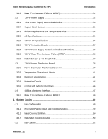
Intel® Server Chassis SC5300 5U Kit TPS Introduction 5.2.9 Clock Generation and Distribution 68 5.2.10 7-Pin SATA/SAS Connector - Drive0-Drive5 69 5.2.11 IPMB Header - IPMB 69 5.2.12 SATA/SAS Host I2C Header - I2C_1 70 5.2.13 Power Budget 70 5.2.14 Board Layout 70 5.2.15 Connector Specifications 71 5.2.16 SATA/SAS Hot Swap Drive Cage Upgrade Kit 72 6. Front Panel ...73 6.1 Front Panel Board Layout 73 6.1.1 Front Panel Connectors 73 6.1.2 6.1.3 Front panel JP2 Header (17x2) Pin-out 74 I2C Connectors at J1 and J2 (Not Installed) Pin-out 75 6.1.4 Front Panel Controls and Indicators 75 6.2 Chassis Interconnect 78 6.3 Chassis Internal Cables 79 6.3.1 Front Panel Cable 79 6.3.2 USB Cable and Connectors 80 6.3.3 Hot Swap Fan Cables and Connectors 80 6.3.4 SCSI Cable 82 6.3.5 Serial Cable 83 6.3.6 SATA Cable 83 6.3.7 6.3.8 IPMB cable for 6-Drive Bays (4-pin 84 I2C Cable for 6-Drive Bays (3-pin 84 7. System-Compatible Server Boards 85 Revision 1.31 5

  • 1
  • 2
  • 3
  • 4
  • 5
  • 6
  • 7
  • 8
  • 9
  • 10
  • 11
  • 12
  • 13
  • 14
  • 15
  • 16
  • 17
  • 18
  • 19
  • 20
  • 21
  • 22
  • 23
  • 24
  • 25
  • 26
  • 27
  • 28
  • 29
  • 30
  • 31
  • 32
  • 33
  • 34
  • 35
  • 36
  • 37
  • 38
  • 39
  • 40
  • 41
  • 42
  • 43
  • 44
  • 45
  • 46
  • 47
  • 48
  • 49
  • 50
  • 51
  • 52
  • 53
  • 54
  • 55
  • 56
  • 57
  • 58
  • 59
  • 60
  • 61
  • 62
  • 63
  • 64
  • 65
  • 66
  • 67
  • 68
  • 69
  • 70
  • 71
  • 72
  • 73
  • 74
  • 75
  • 76
  • 77
  • 78
  • 79
  • 80
  • 81
  • 82
  • 83
  • 84
  • 85
  • 86
  • 87
  • 88
  • 89
  • 90
  • 91
  • 92
  • 93
  • 94
  • 95
  • 96
  • 97
  • 98
  • 99
  • 100
  • 101

Intel® Server Chassis SC5300 5U Kit TPS
Introduction
Revision 1.31
5
5.2.9
Clock Generation and Distribution
.............................................................
68
5.2.10
7-Pin SATA/SAS Connector – Drive0-Drive5
.............................................
69
5.2.11
IPMB Header - IPMB
.................................................................................
69
5.2.12
SATA/SAS Host I
2
C Header - I2C_1
..........................................................
70
5.2.13
Power Budget
............................................................................................
70
5.2.14
Board Layout
..............................................................................................
70
5.2.15
Connector Specifications
...........................................................................
71
5.2.16
SATA/SAS Hot Swap Drive Cage Upgrade Kit
..........................................
72
6.
Front Panel
............................................................................................................
73
6.1
Front Panel Board Layout
..........................................................................
73
6.1.1
Front Panel Connectors
.............................................................................
73
6.1.2
Front panel JP2 Header (17x2) Pin-out
. ....................................................
74
6.1.3
I
2
C Connectors at J1 and J2 (Not Installed) Pin-out
...................................
75
6.1.4
Front Panel Controls and Indicators
...........................................................
75
6.2
Chassis Interconnect
.................................................................................
78
6.3
Chassis Internal Cables
.............................................................................
79
6.3.1
Front Panel Cable
......................................................................................
79
6.3.2
USB Cable and Connectors
.......................................................................
80
6.3.3
Hot Swap Fan Cables and Connectors
......................................................
80
6.3.4
SCSI Cable
................................................................................................
82
6.3.5
Serial Cable
...............................................................................................
83
6.3.6
SATA Cable
...............................................................................................
83
6.3.7
IPMB cable for 6-Drive Bays (4-pin)
...........................................................
84
6.3.8
I
2
C Cable for 6-Drive Bays (3-pin)
..............................................................
84
7.
System-Compatible Server Boards
.....................................................................
85