Intel SE7525RP2 Product Specification - Page 121
Table 92. System Recovery and Update Jumper Options
 |
View all Intel SE7525RP2 manuals
Add to My Manuals
Save this manual to your list of manuals |
Page 121 highlights
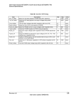
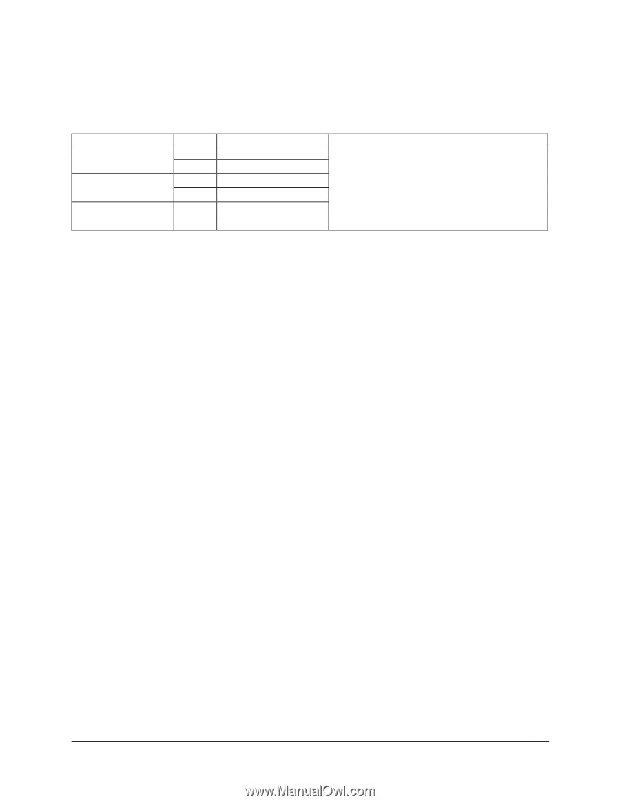
Intel® Server Board SE7320EP2 / Intel® Server Board SE7525RP2 TPS Server Board SE7320EP2 and SE7525RP2 Connectors The following table describes each jumper option. Table 92. System Recovery and Update Jumper Options Function CMOS CLEAR PASSWORD CLEAR RECOVERY BOOT Pin - Pin Function 1-2 Normal Boot 2-3 Force erase 5-6 Protect 6-7 Erase 9-10 Normal Boot 10-11 Recovery BOOT Description These three pins are connected to GPIs of Super I/O. The system BIOS reads these GPIs status and decides whether or not to execute related task. The clear CMOS status is reflected to 6300ESB ICH. Defaults are in bold. Revision 1.0 121 Intel order number D24635-001
-
 1
1 -
2
-
3
-
4
-
5
-
6
-
7
-
8
-
9
-
10
-
11
-
12
-
13
-
14
-
15
-
16
-
17
-
18
-
19
-
20
-
21
-
22
-
23
-
24
-
25
-
26
-
27
-
28
-
29
-
30
-
31
-
32
-
33
-
34
-
35
-
36
-
37
-
38
-
39
-
40
-
41
-
42
-
43
-
44
-
45
-
46
-
47
-
48
-
49
-
50
-
51
-
52
-
53
-
54
-
55
-
56
-
57
-
58
-
59
-
60
-
61
-
62
-
63
-
64
-
65
-
66
-
67
-
68
-
69
-
70
-
71
-
72
-
73
-
74
-
75
-
76
-
77
-
78
-
79
-
80
-
81
-
82
-
83
-
84
-
85
-
86
-
87
-
88
-
89
-
90
-
91
-
92
-
93
-
94
-
95
-
96
-
97
-
98
-
99
-
100
-
101
-
102
-
103
-
104
-
105
-
106
-
107
-
108
-
109
-
110
-
111
-
112
-
113
-
114
-
115
-
 116
116 -
 117
117 -
 118
118 -
 119
119 -
 120
120 -
 121
121 -
 122
122 -
 123
123 -
 124
124 -
 125
125 -
 126
126 -
127
-
128
-
129
-
130
-
131
-
132
 |
 |
Intel® Server Board SE7320EP2 / Intel® Server Board SE7525RP2 TPS
Server Board SE7320EP2 and SE7525RP2 Connectors
Revision 1.0
Intel order number D24635-001
121
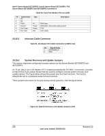
The following table describes each jumper option.
Table 92. System Recovery and Update Jumper Options
Function
Pin – Pin
Function
Description
1-2
Normal Boot
CMOS CLEAR
2-3
Force erase
5-6
Protect
PASSWORD CLEAR
6-7
Erase
9-10
Normal Boot
RECOVERY BOOT
10-11
Recovery BOOT
These three pins are connected to GPIs of Super I/O.
The system BIOS reads these GPIs status and
decides whether or not to execute related task. The
clear CMOS status is reflected to 6300ESB ICH.
Defaults are in bold.